|
Size: 4840
Comment:
|
← Revision 74 as of 2019-11-12 11:32:54 ⇥
Size: 4846
Comment:
|
| Deletions are marked like this. | Additions are marked like this. |
| Line 28: | Line 28: |
| As for the phase noise conversion, we have used L(f) = S(f)/2 where L(f) is that in [dBc/Hz] and S(f) is phase noise in [rad^2^/Hz] according to the IEEE definition. | /!\ As for the phase noise conversion, we have used L(f) = S(f)/2 where L(f) is that in [dBc/Hz] and S(f) is phase noise in [rad^2^/Hz] according to the IEEE definition. |
Low Noise VCOs
Descriptions
Low phase noise, a center frequency of 80 MHz, actuation range of several 100 kHz, aaa dBm output
Prototype model
Designed by Y. Enomoto (2018), aiming at quick implementation, inspired by LIGO low noise VCOs. JGW-D1808968
One unit costed 370,000 JPY. A rough estimation of the cost can be found in the attached spread sheet.
Noise performance
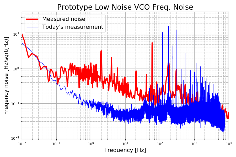
Worse than the specification for the non-divided phase noise (klog 7425) at 1 and 10 kHz. See the table below.
- Most of the RF components are not secured to the chassis in order to allow for the quick implementation. This may cause undesired acoustic coupling.

Frequency [Hz]
Measured noise in [Hz/Hz1/2 ]
that converted in [dBc/Hz]Spec. values without dividers in [Hz/Hz1/2]
and in [dBc/Hz]0.01
5 (51 dBc/Hz)
--
0.1
0.4 (9 dBc/Hz)
--
1
0.1 (-23 dBc/Hz)
--
10
0.05 (-49 dBc/Hz)
--
100
0.05 (-69 dBc/Hz)
--
1,000
0.05 (-89 dBc/Hz)
0.02 (-98 dBc/Hz)
10,000
0.03 (-113 dBc/Hz)
0.01 (-123 dBc/Hz)
100,000
--
0.01 (-143 dBc/Hz)
 As for the phase noise conversion, we have used L(f) = S(f)/2 where L(f) is that in [dBc/Hz] and S(f) is phase noise in [rad2/Hz] according to the IEEE definition.
Tuning Range
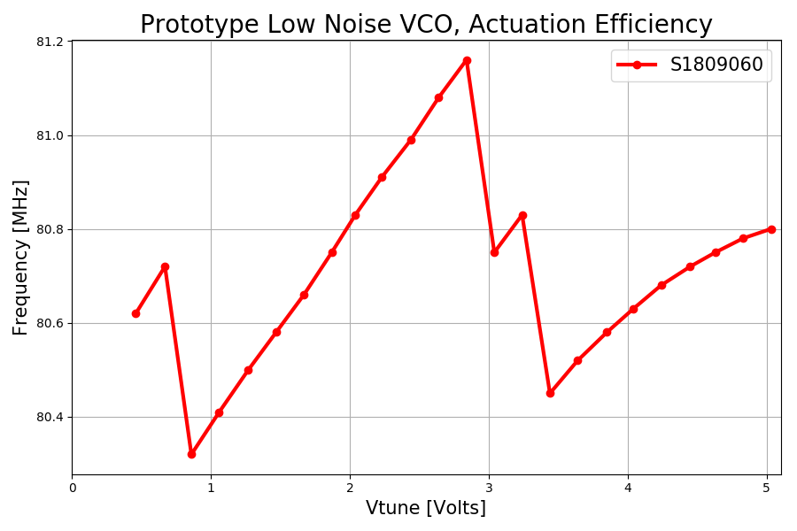
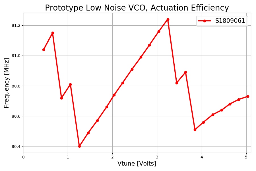
Linear range of 0.8 to 2.8 V achieved (klog 6544, klog 6638). This is smaller than the expected range of 0-5 V.
- Resulting frequency showed some kind of hops, limiting the linear range. No clear explanation exists at the moment.
Tuning sensitivity of 0.42 MHz/V is achieved (klog 6544). This is consistent with the specification of ROS-102-919 whose sensitivity is 4.5 MHz/V typ.


Endeavour model
- Sophisticated version of the prototype model.
- The below is a list of the things that need to be evaluated before building it.
- Determination of whether ROS-102-919 meets the data sheet values in phase noise.
- Identification of where the dominant noise sources are.
- Identification of where the frequency hop comes from.
- Estimate the impact of thermal fluctuation through the push in VCO.
Improvements over the previous version
- Several points will be improved as listed below.
- Mechanically stable mounting by providing an aluminum plate as was done for the RF distribution amplifiers and similar ().
- Any others?
Bill of Materials
Description
Part number
Manufacture
Notes
Price/each
Quantities
Total Price
Procurement/Preparation Status
Seed VCO
ROS-102-919 (with eval.board TB-10)
Minicicruits
center freq. 100 MHz
19,400 JPY
3
arrived (2019/Aug; KI)
RF amp for VCO output
LNBA-0-13-BJ-100-15
Wenzel
$411
2
Order placed (2019/Aug/23rd; KI) and arrived (2019/Nov/8)
RF amp for LO
LNBA-10-23-AE-100-15
Wenzel
+23 dBm output
$448
2
s/a
RF amp for the output signal
LNBDA-2-26-AC-AE-100-15
Wenzel
+26 dBm output
$754
2
s/a
Frequency divider
LNFD2-10-100-13-1-13-15
Wenzel
factor of 10
$486
2
s/a
Low noise Mixer
LNMX-X-X-X
Wenzel
no attenuation
$396
2
s/a
1U Chassis for RF
JGW-D1706470-v1
AEL
2
AEL has several (2019/Jul/18)
Narrow band pass filter
MC80-10-4AA
Lark Engineering
80 MHz
2
-
Aluminum plates for heat sink
needs to be designed
2
-
Low noise power unit for RF
2
-
Ceramic capacitors for noise reduction
RCE5C1H103J1K1H03B
Murata
10 nF
5
SMA barrel connectors
many
SMA right angle connectors
many
