|
Size: 2585
Comment:
|
Size: 2899
Comment:
|
| Deletions are marked like this. | Additions are marked like this. |
| Line 14: | Line 14: |
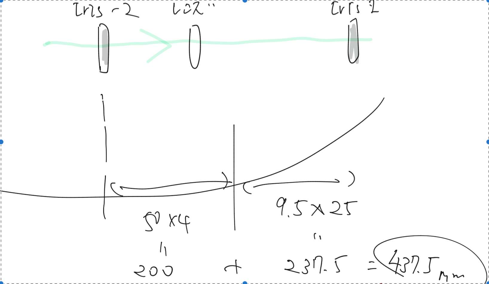
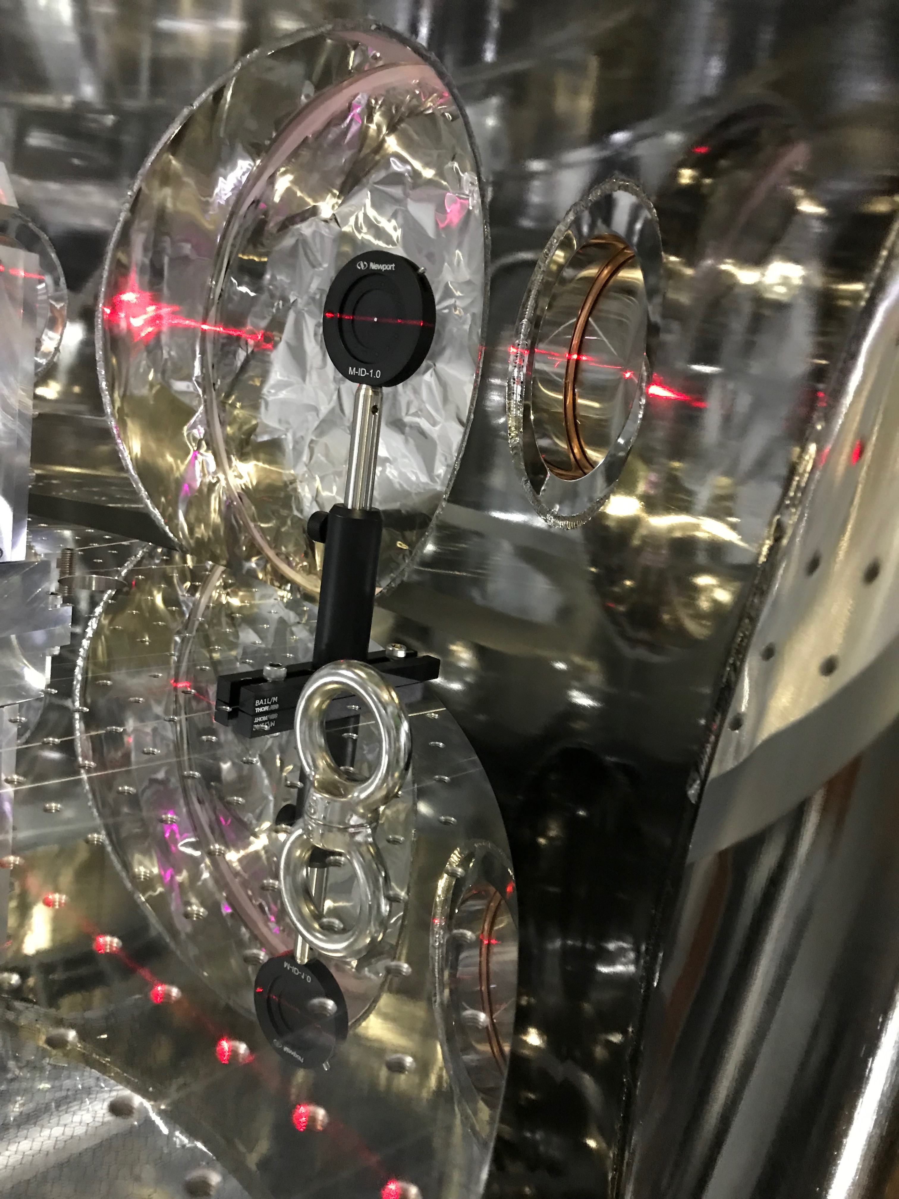
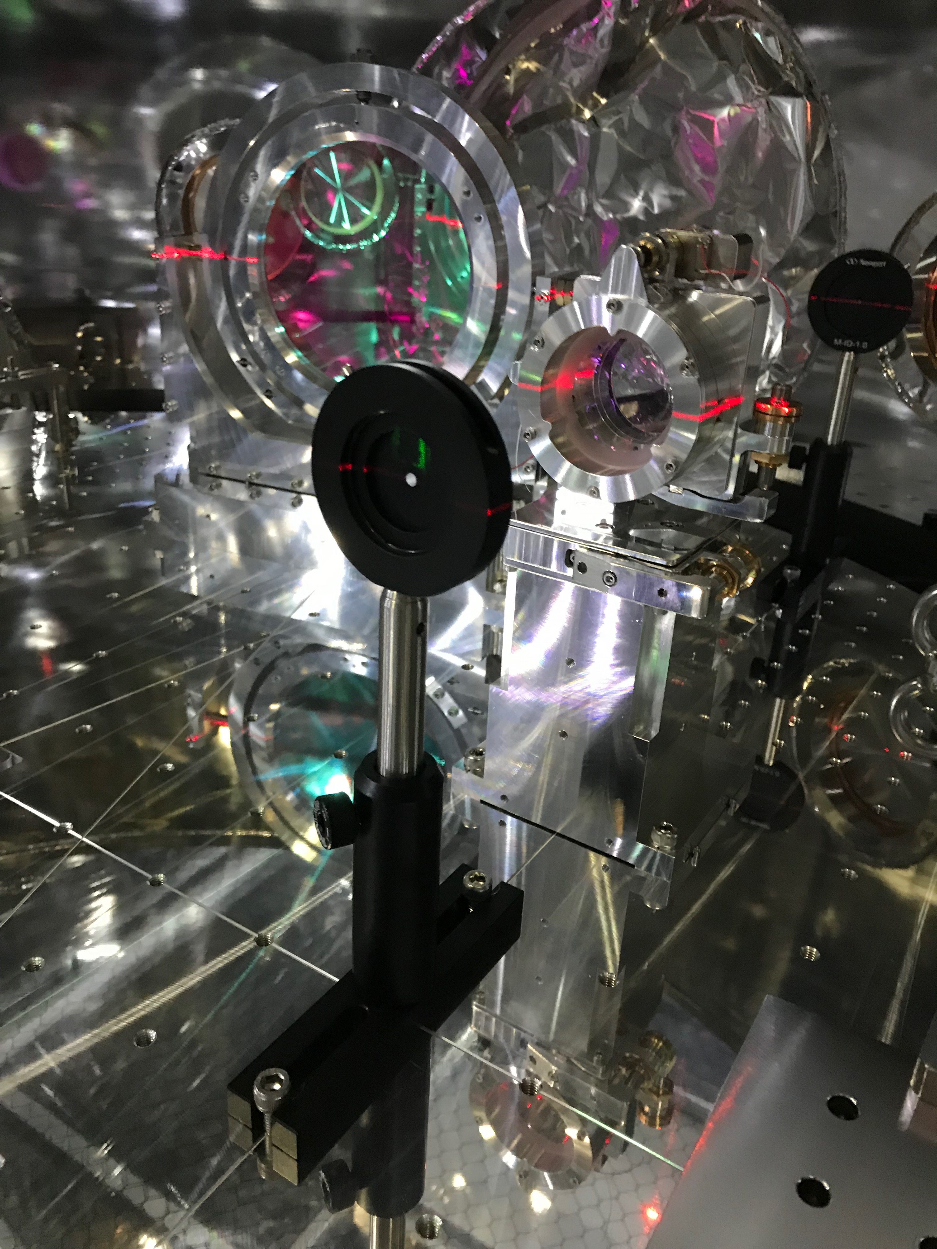
| * Firstly we put two diaphrams; let's call them '''''iris-1''''' and '''''iris-2'''''. The '''''iris-1''''' is at the back of the BRT2 lens, while the '''''iris-2''''' is in front of the BRT2 lens. | * Firstly we put two diaphrams; let's call them '''''iris-1''''' and '''''iris-2'''''. The '''''iris-1''''' is at the back of the BRT2 lens, while the '''''iris-2''''' is in front of the BRT2 lens. The red beam in the following pictures came from a laser level (レーザー墨出器) set on a tripod standing outside of the chamber. The height of the red beam was set so that it shot the center of the irises. As shown in the pics, the green spots were off the centers of the irises at this the first time. |
20181003
Today's activities
Workers: Akutsu, K. Nagano, Aritomi K. Tanaka, Kita
- Akutsu cleaned each side of the optical parts to be installed into the chamber (on the BRT) just using ethanol only. So I omitted acetone and First Contact... Anyway, they are
- CVI's HM-2037-45
- Thorlabs's HBSY21
- Opto Sigma's special one: TFMQSP-50.8C10-20-532/1064-0/26D
- Opto Sigma's SLB-50.8-200NM
Need to make a summary page similar to here.
- Started the alignment of the BRT using the green transmitted beam. It is still on the way.
A reference is here
Firstly we put two diaphrams; let's call them iris-1 and iris-2. The iris-1 is at the back of the BRT2 lens, while the iris-2 is in front of the BRT2 lens. The red beam in the following pictures came from a laser level (レーザー墨出器) set on a tripod standing outside of the chamber. The height of the red beam was set so that it shot the center of the irises. As shown in the pics, the green spots were off the centers of the irises at this the first time.


- On iris
- BBBB
Next plan
Wash an imo-screw for connecting the lens holder and the lower pile.
- Align and balance the BRT and the TMS-VIS.
- Configure the digital models properly.
Clean the sides of the optics to be installed into the vacuum chamber. (Ethanol+Acetone wiping with vectra alpha, then First Contact.) See here.
- Detach the remaining white tapes just before closing the chamber; be noted that there are white tapes on the PEEK connectors at the inside of the flanges.
- Torque completely the bolts which are fixing the upper and the lower base plates.
- Insert metal gaskets before torquing the ICF203 flanges with Dsub connectors.
- Check horizontal actuation
- Calibrate LVDT again
- Put calibration factor of Geophones
- Install Tome-Kanagu for Dsub in DAC0 port #4
- Put tags to cables
- Align BRT
- Start to install GPT part
- Damping of TMS-VIS
Wanted!
- Tester!! lend from DGS or PEM??
- M8 eyebolts for managing the dummy weight plates...
- First contact to clean the side diameter of the optics.
- Need a signal generator for LVDTs
- A document for learning how to release or fix the suspended tables (by Uraguchi?).
- Cable tags
- IR mirrors (4 PYD-20, 3 PYD-10)
- Tome-Kanagu for Dsub
- Power taps
- ONE DAC PORT!!!!
