|
Size: 4509
Comment:
|
Size: 6865
Comment:
|
| Deletions are marked like this. | Additions are marked like this. |
| Line 12: | Line 12: |
| * Started the alignment of the BRT using the green transmitted beam. It is still on the way. | * Prepared the alignment of the BRT using the green transmitted beam. |
| Line 14: | Line 14: |
| * Firstly we put two diaphrams; let's call them '''''iris-1''''' and '''''iris-2'''''. The '''''iris-1''''' is at the back of the BRT2 lens, while the '''''iris-2''''' is in front of the BRT2 lens. The red beam in the following pictures came from a laser level (レーザー墨出器) set on a tripod standing outside of the chamber. The height of the red beam was set so that it shot the center of the irises. As shown in the pics, the green spots were off the centers of the irises at this the first time. And the green beam includes the shadow of the PD (at EXA) in front of ETMX... As the '''''iris-2''''' was closed when we took those pictures, no green spot could be found on the '''''iris-1''''' at this time. | * Firstly we put two diaphrams; let's call them '''''iris-1''''' and '''''iris-2'''''. The iris-1 is at the back of the BRT2 lens, while the iris-2 is in front of the BRT2 lens. The red beam in the following pictures came from a laser level (レーザー墨出器) set on a tripod standing outside of the chamber. The height of the red beam was set so that it shot the center of the irises. As shown in the pics, the green spots were off the centers of the irises at this the first time. And the green beam includes the shadow of the PD (at EXA) in front of ETMX... As the iris-2 was closed when we took those pictures, no green spot could be found on the iris-1 at this time. |
| Line 18: | Line 18: |
| * When we opened the '''''iris-2''''', a green spot appeared on the '''''iris-1''''' as shown in the following picture. Using a metal ruler, we measured the vertical distance of the green spot on the '''''iris-2''''' from its center hole as about +8 mm (as you can understand, this is very rough estimation due to the big spot size and the shadow...), while that on the '''''iris-1''''' was about +23mm, so the displacement was 23-8=15 mm . The distance from '''''iris-2''''' to '''''iris-1''''' was about 437.5 mm, so the vertical tilt (or ''pitch'') of the green beam here was 15/437.5 = 0.034 rad (rising up toward the end). | * When we opened the iris-2, a green spot appeared on the iris-1 as shown in the following picture. Using a metal ruler, we measured the vertical distance of the green spot on the iris-2 from its center hole as about +8 mm (as you can understand, this is very rough estimation due to the big spot size and the shadow...), while that on the iris-1 was about +23mm, so the displacement was 23-8=15 mm . The distance from iris-2 to iris-1 was about 437.5 mm, so the vertical tilt (or ''pitch'') of the green beam here was 15/437.5 = 0.034 rad (rising up toward the end). |
| Line 21: | Line 21: |
| * We also roughly measured the horizontal distances of the spots on the irises; about 3mm away from the center hole in the direction of +Yarm on '''''iris-2''''' and 2mm on '''''iris-1'''''. (3-2)/437.5 = 0.0023 rad. I'm not sure how meaningful this measurement was, as it was difficult to judge the spots postions. Like to check using beam spots without the shadows... | * We also roughly measured the horizontal distances of the spots on the irises; about 3mm away from the center hole in the direction of +Yarm on iris-2 and 2mm on iris-1. (3-2)/437.5 = 0.0023 rad. I'm not sure how meaningful this measurement was, as it was difficult to judge the spots postions. Like to check using beam spots without the shadows... Anyway, the original yaw tilt would be 2.3e-4 rad. The refraction index of sapphire at 532 nm would be about n=1.77, and the wedge angle of the ETMX would be ''theta''_w = 0.05+/-0.01 deg (see [[http://gwwiki.icrr.u-tokyo.ac.jp/JGWwiki/LCGT/subgroup/ifo/MIF/OptParam|here]]), so the yaw angle of the transmitting green beam inputting the primary lens of the BRT would be (n-1)*''theta''_w = 0.0385 deg = 6.7e-4 rad, which is different from the number above by a few factor; the order is consistent though. Probably the read of the spot positions would include more than 1mm so that would affect. Note that the direction of the yaw tilt of the beam is also consistent. Anyway, it is difficult to put the BRT without yaw in this order, so the BRT was just put as was. So the yaw's discussion would not so meaningful. Actually the BRT was put on the TMS-VIS, so it would be interesting to check the LVDT output in yaw of the TMS-VIS. |
| Line 23: | Line 23: |
| * BBBB | * Aligned the '''''pitch''''' as a trial * As the 1/300 pitching is obvisous and reasonable, we tried to compensate this by tweaking the length of each leg (misumi SGKS10-50) of the BRT. * Firstly we measured the length of each sticking-out head by a digital caliper and a metal ruler as shown in the following figure. Note that we measured the head lengths, so larger the number, the BRT is lowered more. {{attachment:leg20181003.jpg|Leglength|width="400" }} * As we wanted to fix something as a reference, determined to leave front two legs as were; note that we don't care about the roll so far. To make 1/300 rising-up toward Xend, 660mm*1/300 = 2.2mm elongation is required. The leg (misumi SGKS10-50) has M10 screws outside, and the pitch of a M10 screw is 1.5mm. So 2.2/1.5= 1.47 screwing would correspond to the 1/300. * So, screwed down in right direction(右ねじまわりに押し込めばよいので。) ~1.5 回転 after fixing the floating table part. The fix was done by attaching three shims to the limitters, and attaching a hamper plate for safety; we found that at least the height and pitch of the table were not changed before and after the fixing. This was estimated from the fact that the red beam from レーザー墨出器 and the both irises' holes were not shifted before and after the fixing. Don't forget loosening the screws that are fixing the plates for the leg parts to the top plate of the TMS-VIS. Without craining up the BRT the leg part can be screwed by hand! {{attachment:IMG_7169.jpg|AfterPitchAdj1|width="400" }} |
20181003
Today's activities
Workers: Akutsu, K. Nagano, Aritomi K. Tanaka, Kita
- Akutsu cleaned each side of the optical parts to be installed into the chamber (on the BRT) just using ethanol only. So I omitted acetone and First Contact... Anyway, they are
- CVI's HM-2037-45
- Thorlabs's HBSY21
- Opto Sigma's special one: TFMQSP-50.8C10-20-532/1064-0/26D
- Opto Sigma's SLB-50.8-200NM
Need to make a summary page similar to here.
- Prepared the alignment of the BRT using the green transmitted beam.
A reference is here
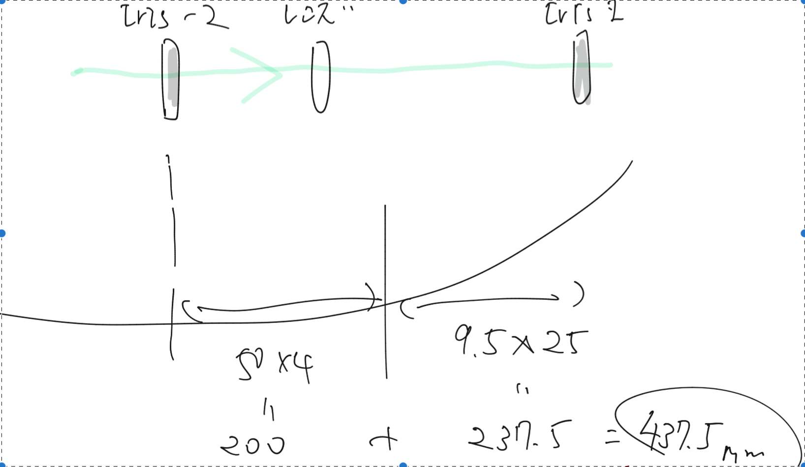
Firstly we put two diaphrams; let's call them iris-1 and iris-2. The iris-1 is at the back of the BRT2 lens, while the iris-2 is in front of the BRT2 lens. The red beam in the following pictures came from a laser level (レーザー墨出器) set on a tripod standing outside of the chamber. The height of the red beam was set so that it shot the center of the irises. As shown in the pics, the green spots were off the centers of the irises at this the first time. And the green beam includes the shadow of the PD (at EXA) in front of ETMX... As the iris-2 was closed when we took those pictures, no green spot could be found on the iris-1 at this time.
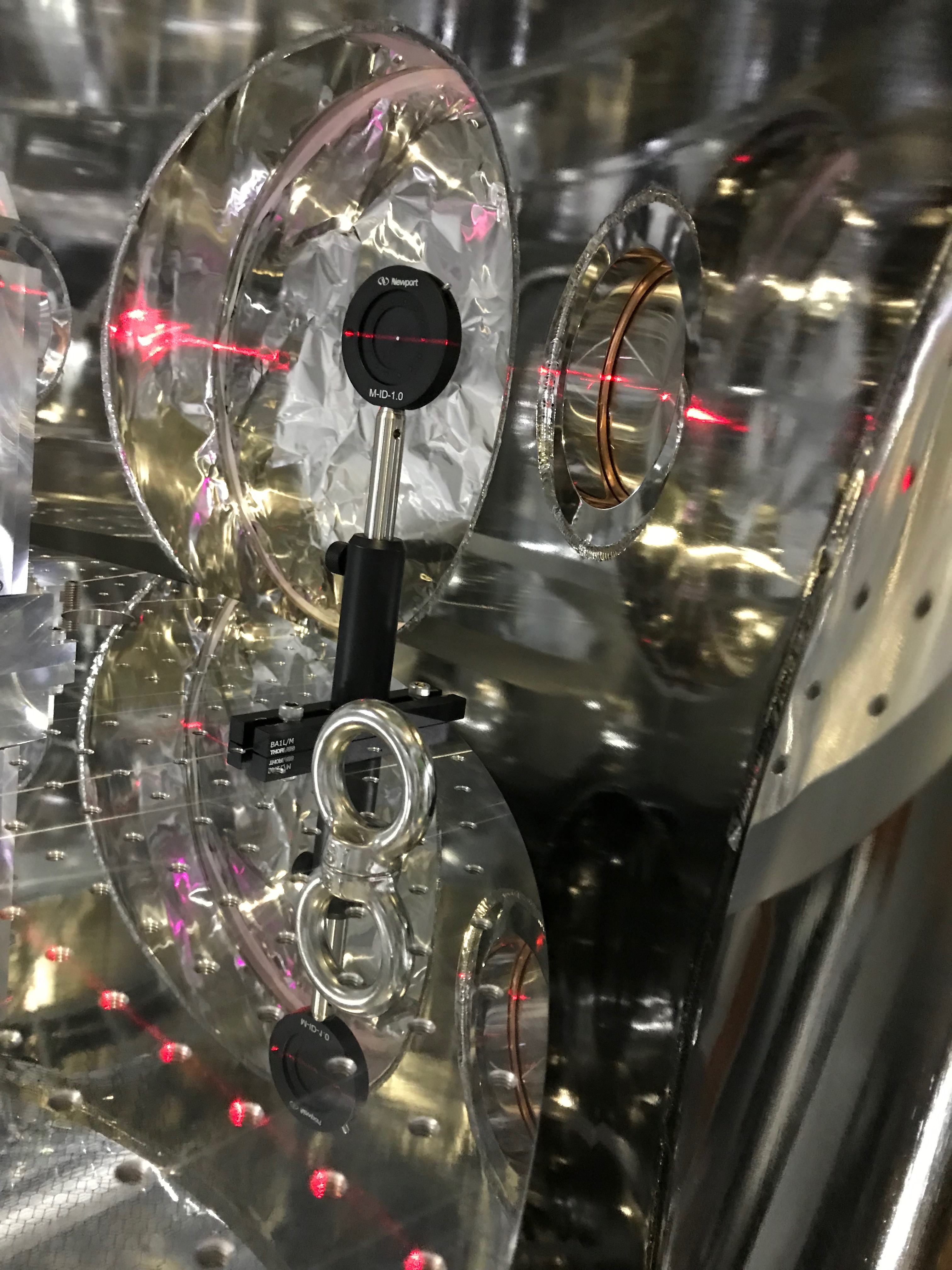
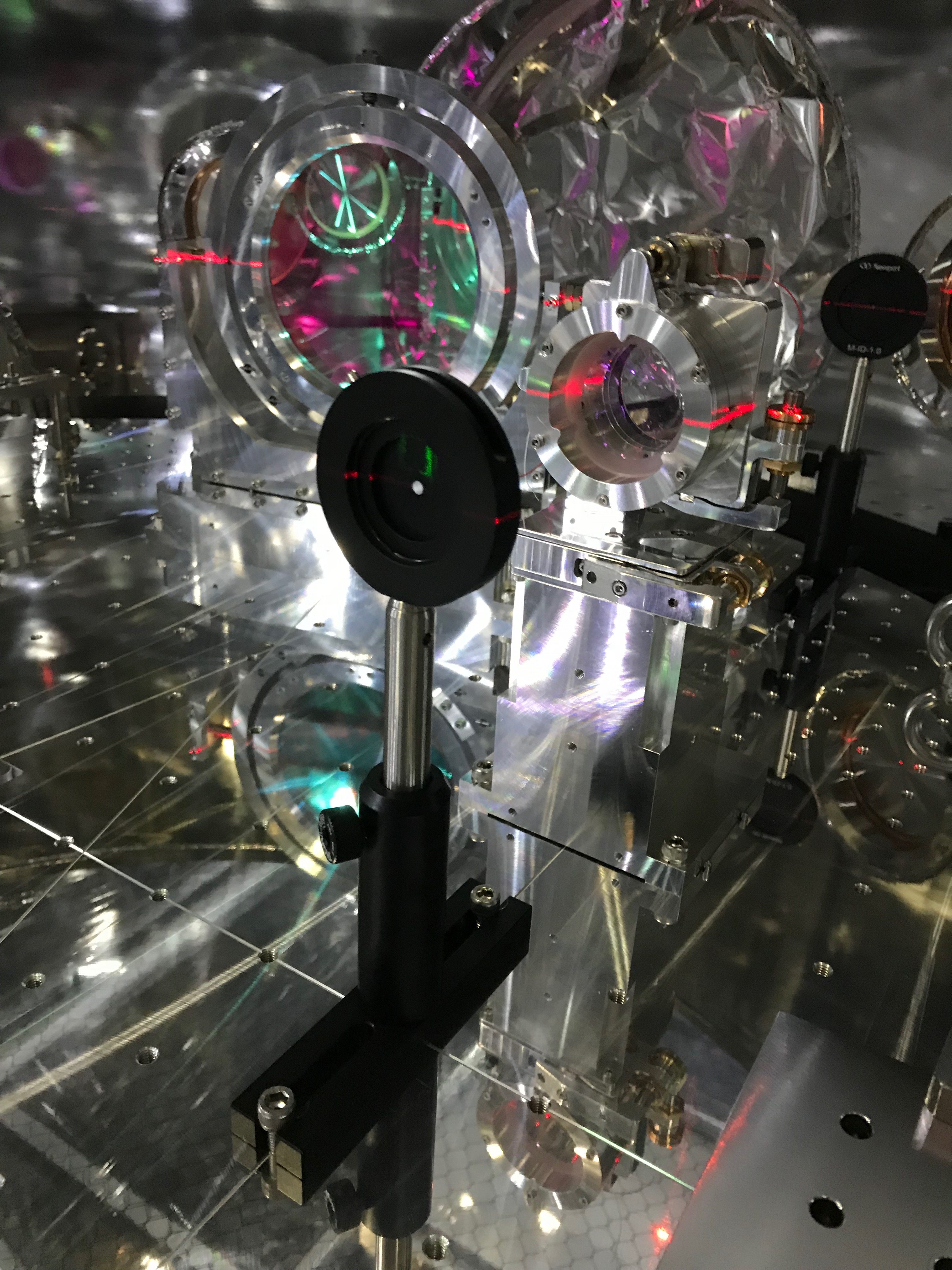
When we opened the iris-2, a green spot appeared on the iris-1 as shown in the following picture. Using a metal ruler, we measured the vertical distance of the green spot on the iris-2 from its center hole as about +8 mm (as you can understand, this is very rough estimation due to the big spot size and the shadow...), while that on the iris-1 was about +23mm, so the displacement was 23-8=15 mm . The distance from iris-2 to iris-1 was about 437.5 mm, so the vertical tilt (or pitch) of the green beam here was 15/437.5 = 0.034 rad (rising up toward the end).
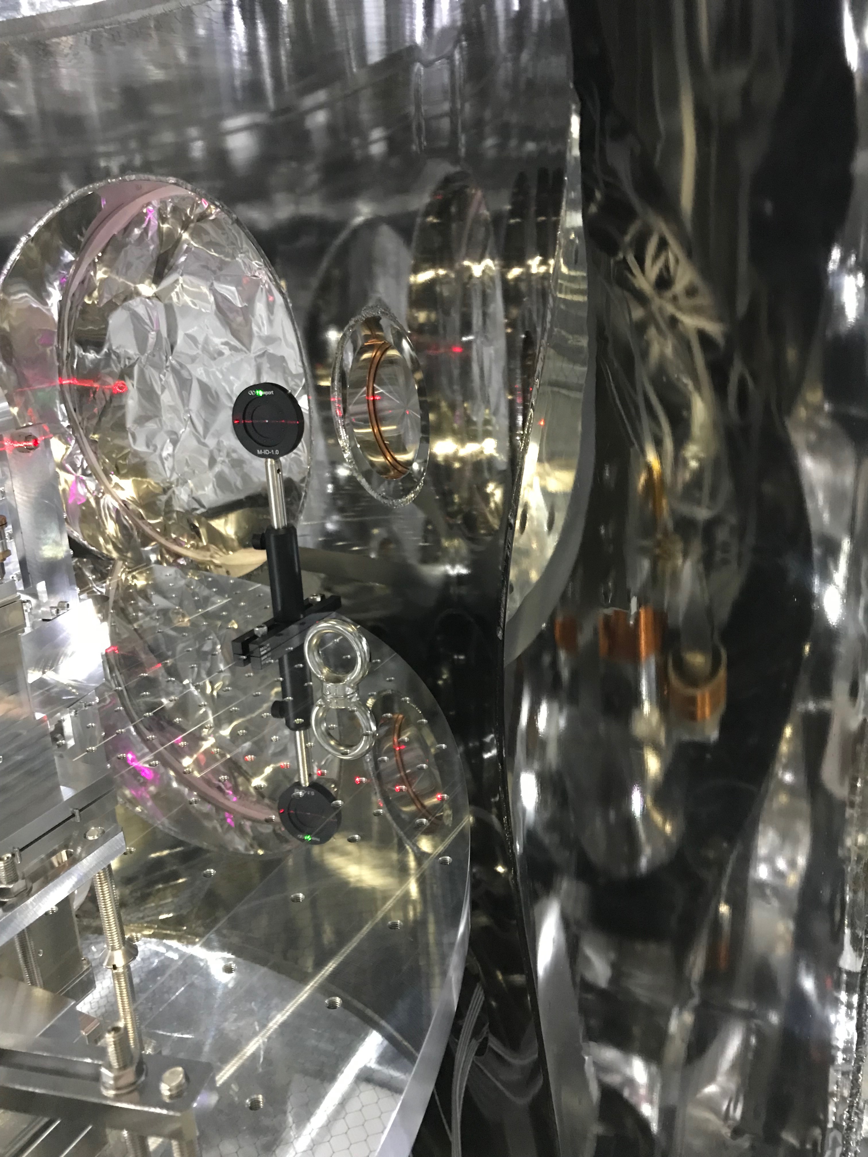
As already discussed here, the BRT is to reduce the size of the beam 1/10, so the original tilt of the entering optical beam would become 10 times, which means teh 0.034 rad would be originally 0.003 rad pitch. This is consistent with the 1/300 rising of the beam to Xend.
We also roughly measured the horizontal distances of the spots on the irises; about 3mm away from the center hole in the direction of +Yarm on iris-2 and 2mm on iris-1. (3-2)/437.5 = 0.0023 rad. I'm not sure how meaningful this measurement was, as it was difficult to judge the spots postions. Like to check using beam spots without the shadows... Anyway, the original yaw tilt would be 2.3e-4 rad. The refraction index of sapphire at 532 nm would be about n=1.77, and the wedge angle of the ETMX would be theta_w = 0.05+/-0.01 deg (see here), so the yaw angle of the transmitting green beam inputting the primary lens of the BRT would be (n-1)*theta_w = 0.0385 deg = 6.7e-4 rad, which is different from the number above by a few factor; the order is consistent though. Probably the read of the spot positions would include more than 1mm so that would affect. Note that the direction of the yaw tilt of the beam is also consistent. Anyway, it is difficult to put the BRT without yaw in this order, so the BRT was just put as was. So the yaw's discussion would not so meaningful. Actually the BRT was put on the TMS-VIS, so it would be interesting to check the LVDT output in yaw of the TMS-VIS.
Aligned the pitch as a trial
- As the 1/300 pitching is obvisous and reasonable, we tried to compensate this by tweaking the length of each leg (misumi SGKS10-50) of the BRT.
- Firstly we measured the length of each sticking-out head by a digital caliper and a metal ruler as shown in the following figure. Note that we measured the head lengths, so larger the number, the BRT is lowered more.
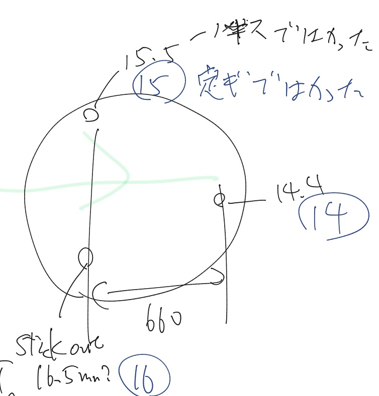
- As we wanted to fix something as a reference, determined to leave front two legs as were; note that we don't care about the roll so far. To make 1/300 rising-up toward Xend, 660mm*1/300 = 2.2mm elongation is required. The leg (misumi SGKS10-50) has M10 screws outside, and the pitch of a M10 screw is 1.5mm. So 2.2/1.5= 1.47 screwing would correspond to the 1/300.
- So, screwed down in right direction(右ねじまわりに押し込めばよいので。) ~1.5 回転 after fixing the floating table part. The fix was done by attaching three shims to the limitters, and attaching a hamper plate for safety; we found that at least the height and pitch of the table were not changed before and after the fixing. This was estimated from the fact that the red beam from レーザー墨出器 and the both irises' holes were not shifted before and after the fixing. Don't forget loosening the screws that are fixing the plates for the leg parts to the top plate of the TMS-VIS. Without craining up the BRT the leg part can be screwed by hand!

Next plan
Wash an imo-screw for connecting the lens holder and the lower pile.
- Align and balance the BRT and the TMS-VIS.
- Configure the digital models properly.
Clean the sides of the optics to be installed into the vacuum chamber. (Ethanol+Acetone wiping with vectra alpha, then First Contact.) See here.
- Detach the remaining white tapes just before closing the chamber; be noted that there are white tapes on the PEEK connectors at the inside of the flanges.
- Torque completely the bolts which are fixing the upper and the lower base plates.
- Insert metal gaskets before torquing the ICF203 flanges with Dsub connectors.
- Check horizontal actuation
- Calibrate LVDT again
- Put calibration factor of Geophones
- Install Tome-Kanagu for Dsub in DAC0 port #4
- Put tags to cables
- Align BRT
- Start to install GPT part
- Damping of TMS-VIS
Wanted!
- Tester!! lend from DGS or PEM??
- M8 eyebolts for managing the dummy weight plates...
- First contact to clean the side diameter of the optics.
- Need a signal generator for LVDTs
- A document for learning how to release or fix the suspended tables (by Uraguchi?).
- Cable tags
- IR mirrors (4 PYD-20, 3 PYD-10)
- Tome-Kanagu for Dsub
- Power taps
- ONE DAC PORT!!!!
