|
Size: 2670
Comment:
|
Size: 2712
Comment:
|
| Deletions are marked like this. | Additions are marked like this. |
| Line 2: | Line 2: |
| * [[]] | * [[http://klog.icrr.u-tokyo.ac.jp/osl/?r=6452]] |
| Line 18: | Line 18: |
| {{attachment:GPM1.png|GPM1|width="400" }} | {{attachment:GPM1.jpg|GPM1|width="400" }} |
| Line 20: | Line 20: |
| {{attachment:GPM2.png|GPM2|width="400" }} | {{attachment:GPM2.jpg|GPM2|width="400" }} |
| Line 22: | Line 22: |
| {{attachment:GST1.png|GST1|width="400" }} | {{attachment:GST1.jpg|GST1|width="400" }} |
| Line 24: | Line 24: |
| {{attachment:GST2.png|GST2|width="400" }} | {{attachment:GST2.jpg|GST2|width="400" }} |
| Line 26: | Line 26: |
| {{attachment:GLNS1.png|GLNS1|width="400" }} | {{attachment:GLNS1.jpg|GLNS1|width="400" }} |
| Line 30: | Line 30: |
| {{attachment:GPD_gain.png|GPD|width="400" }} | {{attachment:GPD_gain.jpg|GPD|width="400" }} |
| Line 32: | Line 32: |
| {{attachment:Overview.png|overview|width="400" }} * The signal was checked [[http://klog.icrr.u-tokyo.ac.jp/osl/?r=6452|like this]]. |
{{attachment:Overview.jpg|overview|width="400" }} * The signal was checked like [[http://klog.icrr.u-tokyo.ac.jp/osl/?r=6452|this]]. |
20181006
Today's activities
Workers: Akutsu, K. Nagano
BRT part installation
- Akutsu-san will report
GPT part installation
- We brought five QPD mechanical basis with plastic case which was used to store Dsub cables.
- AFTER QPD INSTALLATION, WE SHOULD RETURN THE BOX TO 低音鏡機械室.
- After BRT part was installed and aligned, we started to install GPT part (in-air part).
- We found that damping of TMS-VIS was not necessary for GPT installation.
Following the design, we installed the beginning part of the green light path, two periscope mirrors, two steering mirrors, and one lenses.
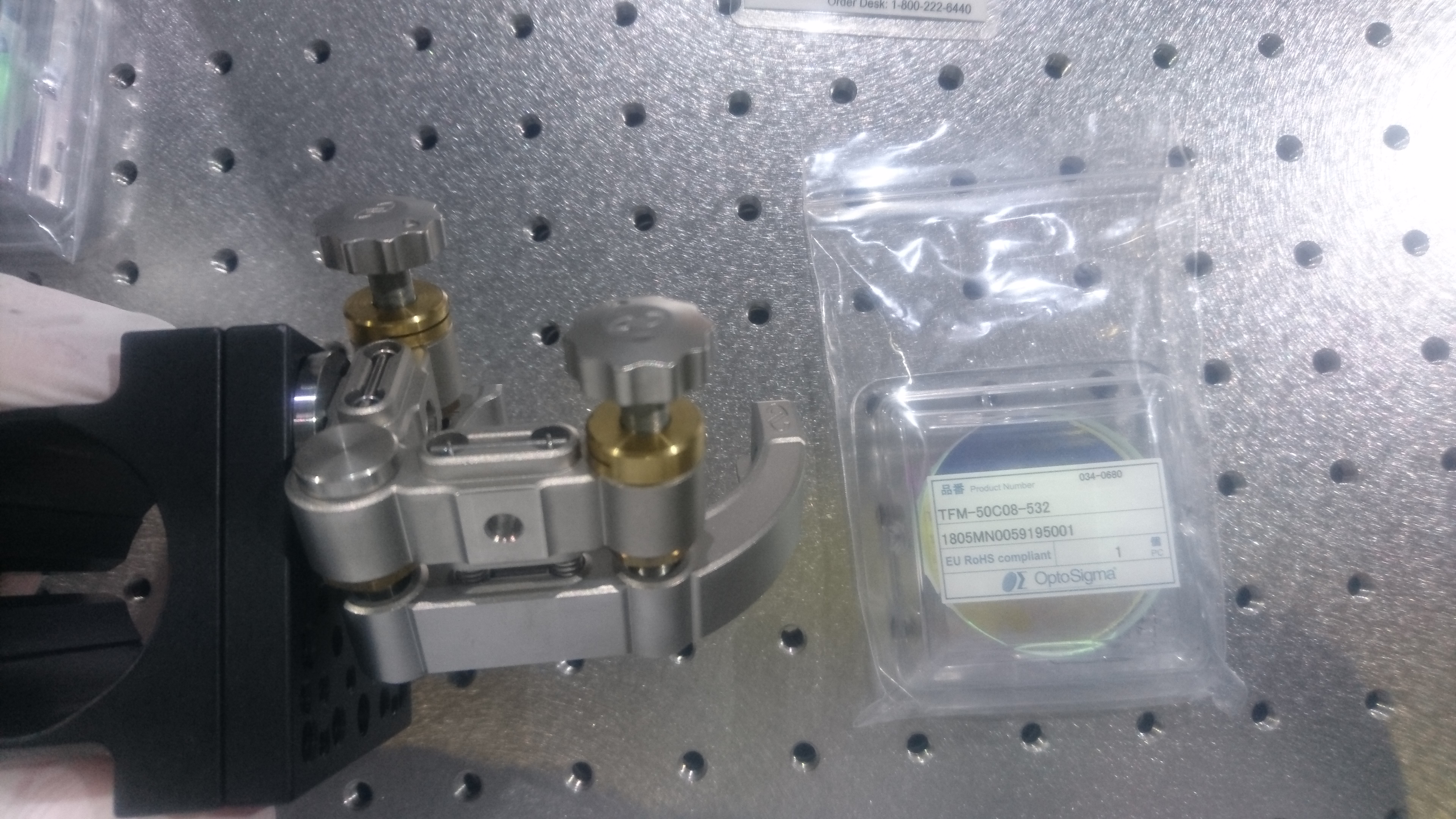
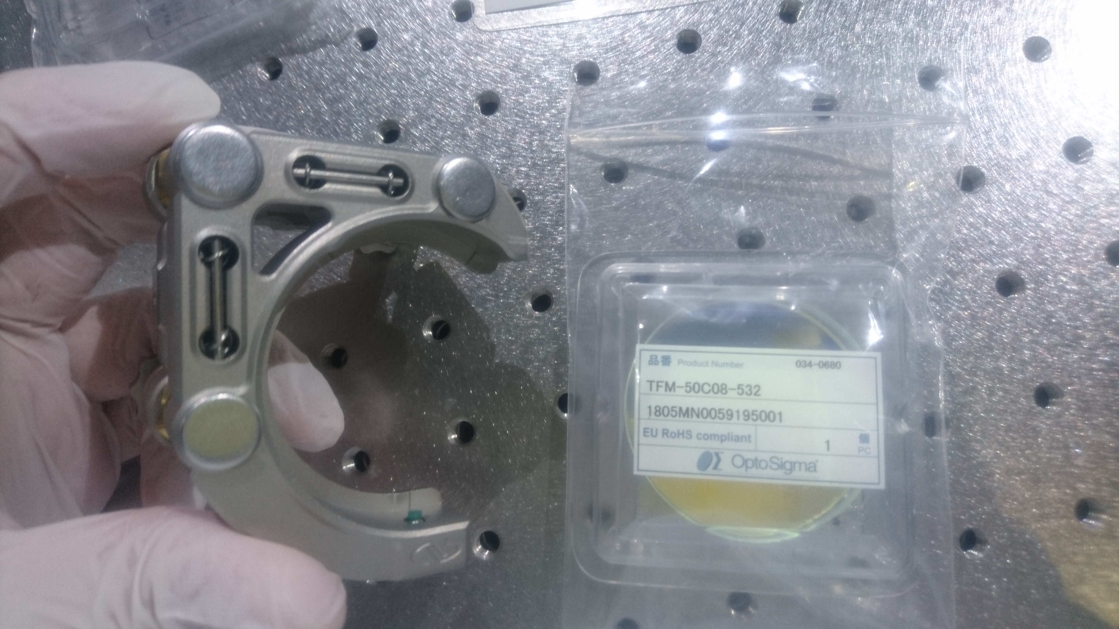
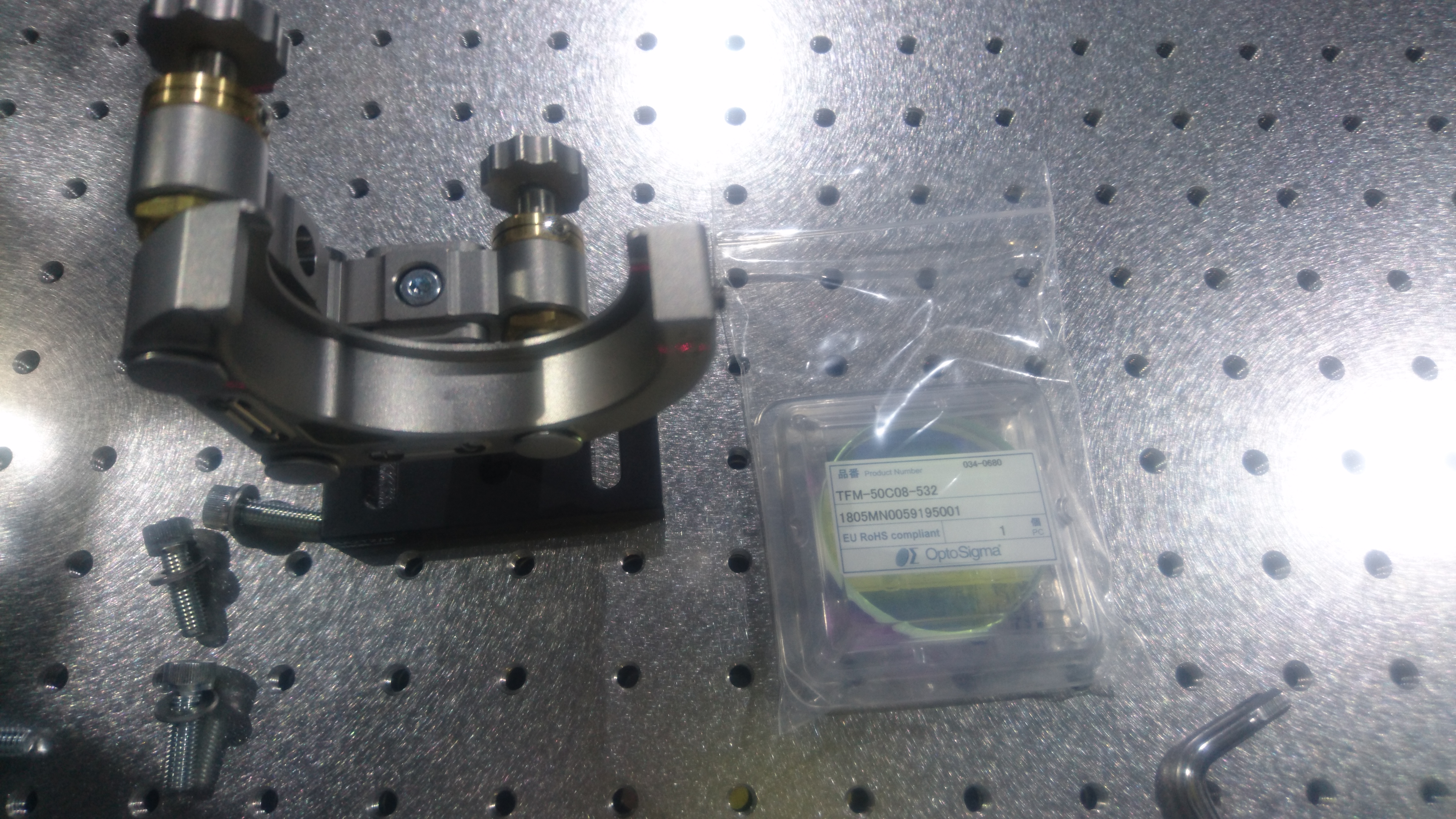
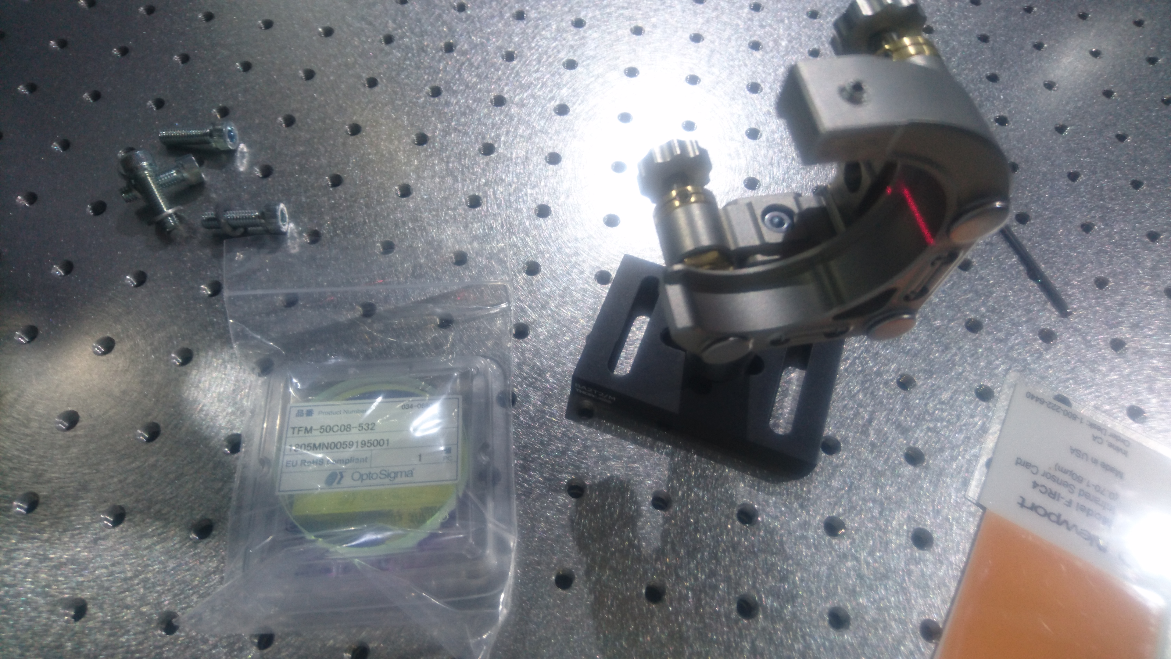
- First periscope mirror (GPM1)
- Second periscope mirror (GPM2)
- First steering mirror (GST1)
- Second steering mirror (GST2)
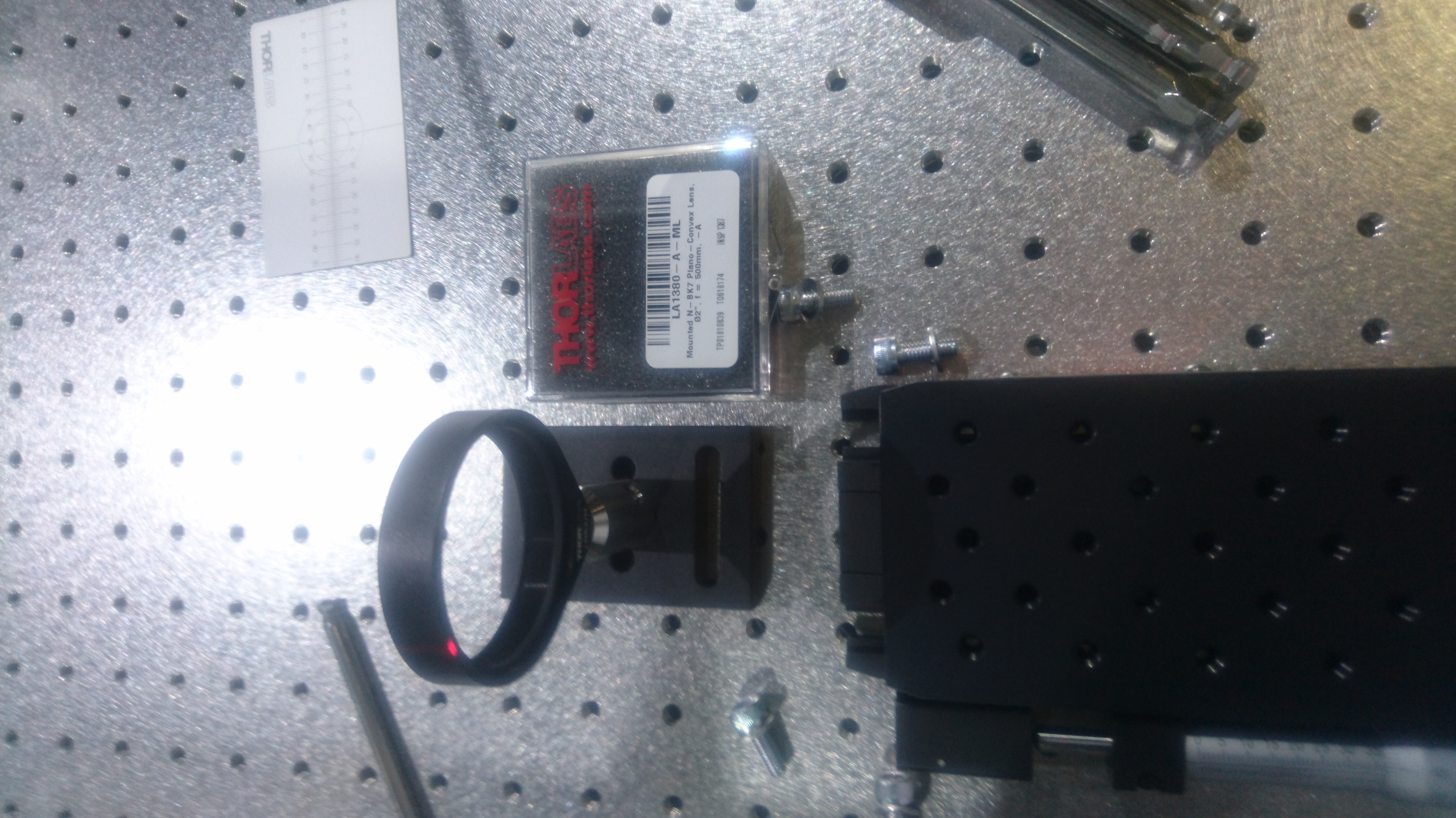
- First lens (GLNS1, f=500)
- First periscope mirror (GPM1)
- At first, all mirrors were installed. Then the lens was installed not to change beam position.
- The lens position, i.e. beam profile, was not tuned since the tuning was not so effective without arm cavity locked.
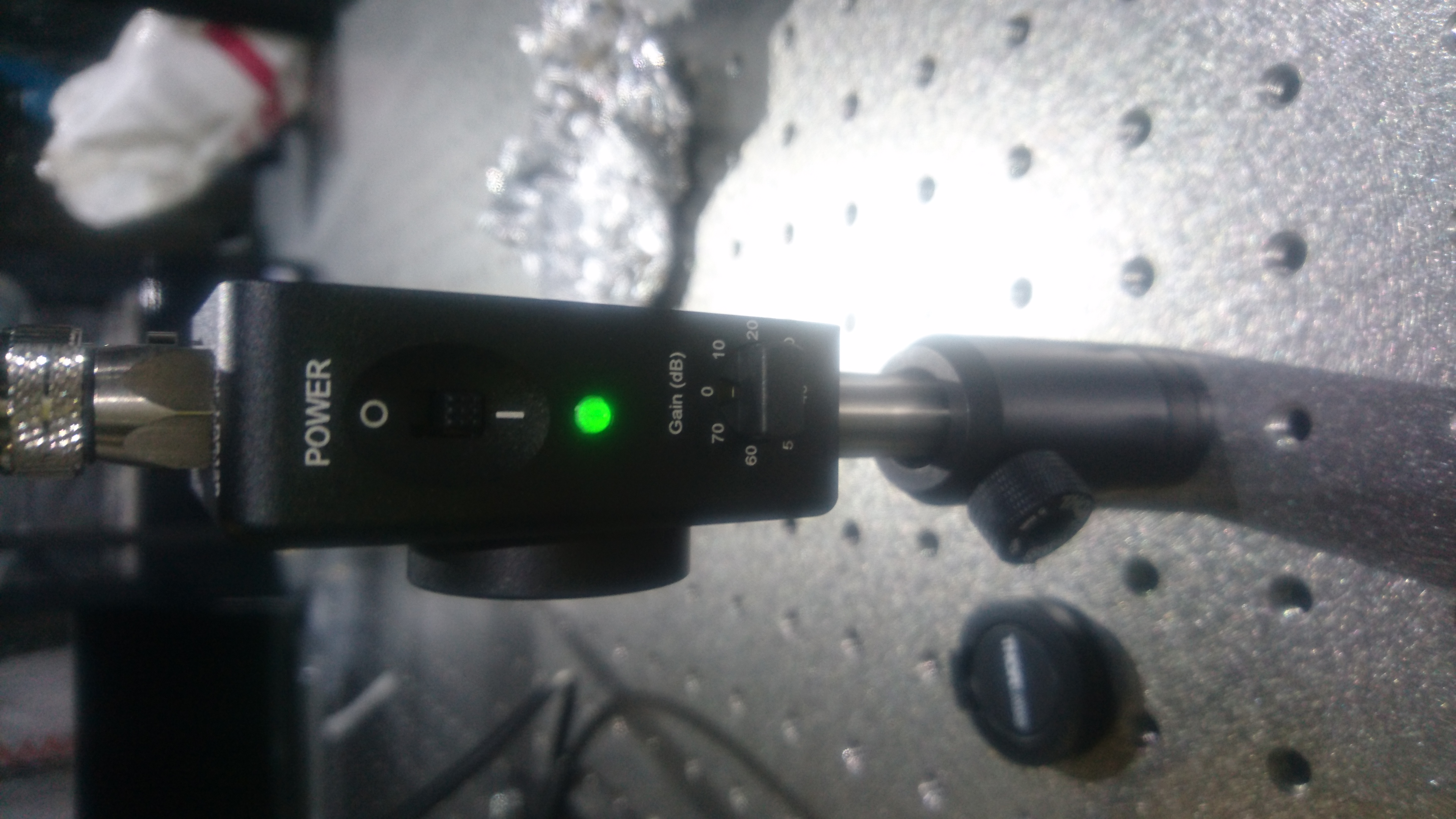
- In the end of today's work, we installed DC PD after GST2 temporarily. The gain was set to 0 dB.
- After all, GPT part looks like below.
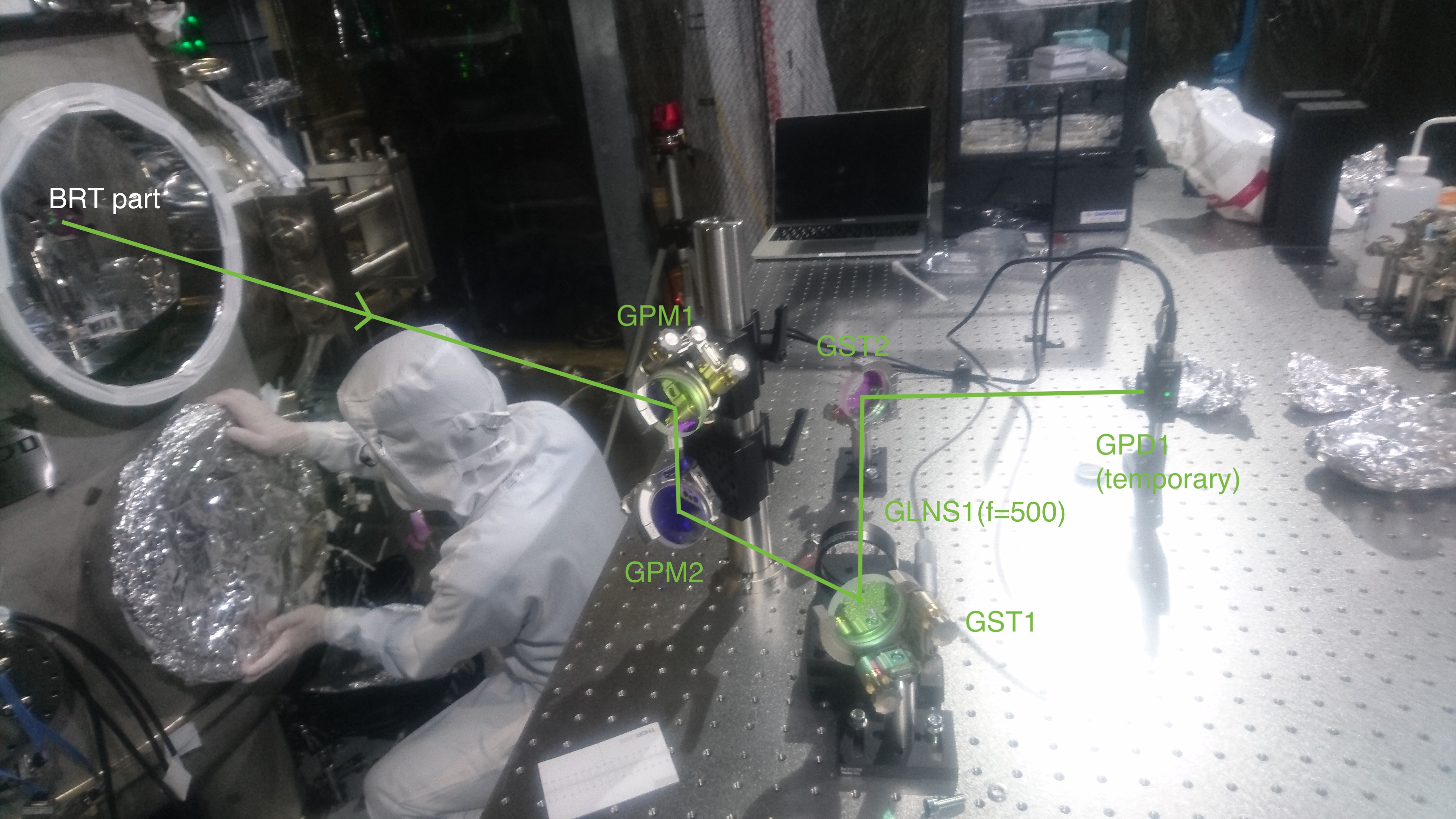
The signal was checked like this.
Next plan
- Align and balance the BRT and the TMS-VIS.
- Configure the digital models properly.
- Detach the remaining white tapes just before closing the chamber; be noted that there are white tapes on the PEEK connectors at the inside of the flanges.
- Torque completely the bolts which are fixing the upper and the lower base plates.
- Insert metal gaskets before torquing the ICF203 flanges with Dsub connectors.
- Install optics after GBS1
- Install gigE camera
- Modify MEDM screen
- Add DC PD and so on.
Cable Dsub 15pin for TMS-VIS OpLev.
- Modify cabling for DC PD.
- Return plastic box.
- Install rails in digital rack.
- They may be necessary under LVDT distributor, geophone distributor, and WHT board.
- Nagano is not sure it is necessary under HP coil driver.
Wanted!
- A document for learning how to release or fix the suspended tables (by Uraguchi?).
- FIVE QPD electronics boards

