|
Size: 291
Comment:
|
Size: 275
Comment:
|
| Deletions are marked like this. | Additions are marked like this. |
| Line 2: | Line 2: |
| There is no special electronics near this reference point [[attachment:ex0.jpg|jpg]] |
behind EX0 rack [[attachment:ex0_2.jpg|jpg]] |
| Line 5: | Line 5: |
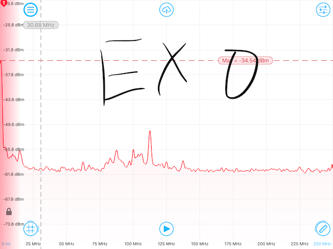
| 0-250 MHz [[attachment:ex0_0_250.jpg|jpg]] |
= 0-250 MHz = {{attachment:ex0_0_250_2.jpg|jpg}} |
| Line 8: | Line 8: |
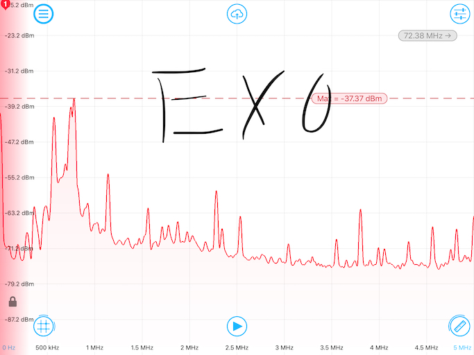
| 0-5 MHz [[attachment:ex0_0_5.jpg|jpg]] |
= 0-5 MHz = {{attachment:ex0_0_5_2.jpg|jpg}} |
| Line 11: | Line 11: |
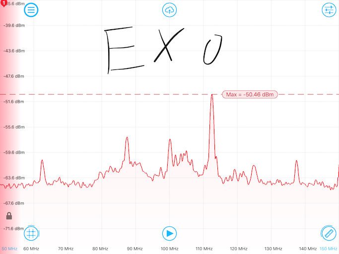
| 50-150 MHz [[attachment:ex0_50_150.jpg|jpg]] |
= 50-150 MHz = {{attachment:ex0_50_150_2.jpg|jpg}} |
| Line 14: | Line 14: |
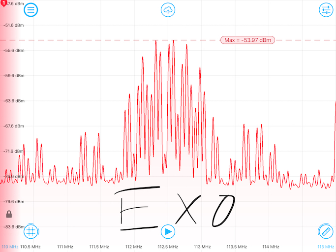
| 110-115 MHz [[attachment:ex0_110_115.jpg|jpg]] |
= 110-115 MHz = {{attachment:ex0_110_115_2.jpg|jpg}} |
- Diff for "KAGRA/Subgroups/PEM/Reports/RFMeasurement/EX0"


