|
Size: 218
Comment:
|
Size: 3949
Comment:
|
| Deletions are marked like this. | Additions are marked like this. |
| Line 5: | Line 5: |
| * [[https://gwdoc.icrr.u-tokyo.ac.jp/cgi-bin/private/DocDB/ShowDocument?docid=5788| JGW-T1605788 Length-Sensing OpLevs for KAGRA]] - writeup by Simon | * [[https://gwdoc.icrr.u-tokyo.ac.jp/cgi-bin/private/DocDB/ShowDocument?docid=5788| JGW-T1605788]] - Length-Sensing !OpLevs for KAGRA, writeup by Simon * [[https://gwdoc.icrr.u-tokyo.ac.jp/cgi-bin/private/DocDB/ShowDocument?docid=3946| JGW-T1503946]] - !OpLev, writeup by Ettore Majorana of VIRGO == Data == * [[KAGRA/Subgroups/AOS/DCQPDList]] - Inventory of QPDs for OLs == Quadrants == {{attachment:QPD Segment Numbering.png| |width = 200}} == Default OL2EUL Matrix == The following matrix is appropriate if the OL beam is bounced off the AR side of the optic. Then, positive pitch of the optic (right-handed around transverse, nose-down) gives a high return beam, more light on SEG3 and SEG4, and positive P. Similarly, positive yaw of the optic (right-handed around vertical, nose-left) gives a return beam offset to the left (looking at the QPD), more light on SEG1 and SEG4, and positive Y. {{attachment:QPD Default OL2EUL matrix.png| |width = 300}} == Micrometer Function == ||Horizontal|| Vertical||Notes|| ||Points right||Points down||viewed facing QPD|| ||Anticlockwise||Anticlockwise||turn of micrometer knob|| ||Retracts tip||Retracts tip|| || ||Larger numbers||Larger numbers||on micrometer scale|| ||Stage moves with tip||Stage moves with body|| || ||QPD moves left||QPD moves down|| || ||Spot moves to right quadrants||Spot moves to upper quadrants|| || ||Simulates -yaw||Simulates +pitch|| || == Mechanical Installation == See [[https://gwdoc.icrr.u-tokyo.ac.jp/cgi-bin/private/DocDB/ShowDocument?docid=8528|D1808528]] for the TX stand and [[https://gwdoc.icrr.u-tokyo.ac.jp/cgi-bin/private/DocDB/ShowDocument?docid=8529|D1808529]] for the shelf, but note that the screw lists are missing the attachment screws. '''Be sure to get all fasteners from AOL stock.''' === Stand Installation === ==== Parts ==== * 1 pillar (pre-assembled) * 1 interface plate * 1 300x400 mm breadboard ==== Screws ==== 6 x M8x20 6 M8 washers 3 x M12x150 threaded rod 9 x M12 nut 9 x M12 washer ==== Procedure ==== * Clean the foot of the white frame where the pillar is to be mounted with wipes to remove dust and particles, and blow out the holes with the airgun. * Orient the pillar so that one of the three M12 threaded holes in the top plate is towards the tank and the other two are away from the tank. * Bolt the pillar down firmly with 6 x M8*20 with washers. If necessary, use ethanol to lubricate the screws during insertion (there may be paint residue in the holes). Check that the pillar does not rock and that the top plate is reasonably level. * There are six Ø12 mm holes in the interface plate. Choose three in a pattern matching the holes in the pillar top plate. * Put M12 lock nuts and washer on the ends of the three M12x150 rods, leaving about 20 mm to the end. * Screw the three M12x150 rods into the interface plate from underneath until the ends are slightly below flush with the top surface. (They must not protrude above the surface, or the breadboard will not sit properly flat.) * Screw the lock washers up to lock the rods into position. * Add M12 lock nuts to the lower ends of the rods, leaving about 60 mm to the ends. Place M12 washers on the pillar top plate around the Ø12 mm holes. * Stand the interface plate on top of the pillar so that the rods go through the holes and the lock nuts sit on the washers. Adjust the lock nuts until the interface plate is level and there is a gap of 74.6 mm between the plates. * Add M12 washers and M12 lock nuts to the bottom of the rods and tighten. * Attach the breadboard with 4 x M6x20 with M6 washers inserted from below in the corners. (Note that for no good reason the TX breadboard uses M6x20 and the RX one uses M6x30. Do use the prescribed size to prevent confusion about stock levels.) === Shelf Installation === |
KAGRA VIS Operations Manual - Optical Levers
Info
JGW-T1605788 - Length-Sensing OpLevs for KAGRA, writeup by Simon
JGW-T1503946 - OpLev, writeup by Ettore Majorana of VIRGO
Data
KAGRA/Subgroups/AOS/DCQPDList - Inventory of QPDs for OLs
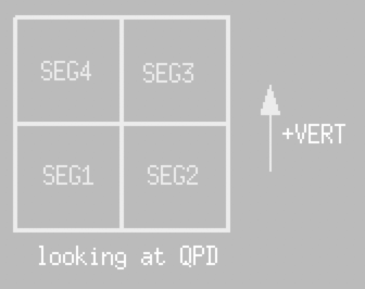
Quadrants

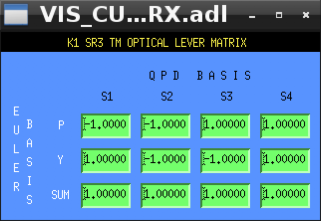
Default OL2EUL Matrix
The following matrix is appropriate if the OL beam is bounced off the AR side of the optic. Then, positive pitch of the optic (right-handed around transverse, nose-down) gives a high return beam, more light on SEG3 and SEG4, and positive P. Similarly, positive yaw of the optic (right-handed around vertical, nose-left) gives a return beam offset to the left (looking at the QPD), more light on SEG1 and SEG4, and positive Y.

Micrometer Function
Horizontal |
Vertical |
Notes |
Points right |
Points down |
viewed facing QPD |
Anticlockwise |
Anticlockwise |
turn of micrometer knob |
Retracts tip |
Retracts tip |
|
Larger numbers |
Larger numbers |
on micrometer scale |
Stage moves with tip |
Stage moves with body |
|
QPD moves left |
QPD moves down |
|
Spot moves to right quadrants |
Spot moves to upper quadrants |
|
Simulates -yaw |
Simulates +pitch |
|
Mechanical Installation
See D1808528 for the TX stand and D1808529 for the shelf, but note that the screw lists are missing the attachment screws.
Be sure to get all fasteners from AOL stock.
Stand Installation
Parts
- 1 pillar (pre-assembled)
- 1 interface plate
- 1 300x400 mm breadboard
Screws
6 x M8x20 6 M8 washers 3 x M12x150 threaded rod 9 x M12 nut 9 x M12 washer
Procedure
- Clean the foot of the white frame where the pillar is to be mounted with wipes to remove dust and particles, and blow out the holes with the airgun.
- Orient the pillar so that one of the three M12 threaded holes in the top plate is towards the tank and the other two are away from the tank.
- Bolt the pillar down firmly with 6 x M8*20 with washers. If necessary, use ethanol to lubricate the screws during insertion (there may be paint residue in the holes). Check that the pillar does not rock and that the top plate is reasonably level.
- There are six Ø12 mm holes in the interface plate. Choose three in a pattern matching the holes in the pillar top plate.
- Put M12 lock nuts and washer on the ends of the three M12x150 rods, leaving about 20 mm to the end.
- Screw the three M12x150 rods into the interface plate from underneath until the ends are slightly below flush with the top surface. (They must not protrude above the surface, or the breadboard will not sit properly flat.)
- Screw the lock washers up to lock the rods into position.
- Add M12 lock nuts to the lower ends of the rods, leaving about 60 mm to the ends. Place M12 washers on the pillar top plate around the Ø12 mm holes.
- Stand the interface plate on top of the pillar so that the rods go through the holes and the lock nuts sit on the washers. Adjust the lock nuts until the interface plate is level and there is a gap of 74.6 mm between the plates.
- Add M12 washers and M12 lock nuts to the bottom of the rods and tighten.
- Attach the breadboard with 4 x M6x20 with M6 washers inserted from below in the corners. (Note that for no good reason the TX breadboard uses M6x20 and the RX one uses M6x30. Do use the prescribed size to prevent confusion about stock levels.)
