|
Size: 7937
Comment:
|
Size: 7937
Comment:
|
| Deletions are marked like this. | Additions are marked like this. |
| Line 110: | Line 110: |
| Setting the parameters trought the web-server: | Setting the parameters through the web-server: |
KAGRA VIS Operations Manual - Setup and Use of Stepper Motor Drivers
Back to Operation Manual main page
The stepper motor chassis designed by Kamiizumi-san has a TMCM-6110 driver card and a NPort® 5150A serial-Internet interface. See D1605365. Sekiguchi-san has written a document in Japanese - this page is an English version of the good bits plus a bit extra specific to KAGRA.
Provisional IP number allocation
Yamamoto-san has allocated a block of IP numbers for stepper drivers, starting at 10.68.150.50. As stepper driver boxes are added, please add them to the following table. Type B suspensions definitely use 2 boxes each. Shoda-san and Takahashi-san need to confirm for Type Bp and Type A.
JGW |
Suspension |
Chassis |
IP |
Type B |
|||
BS |
0 |
10.68.150.50 |
|
BS |
1 |
10.68.150.51 |
|
SR2 |
0 |
10.68.150.52 |
|
SR2 |
1 |
10.68.150.53 |
|
SR3 |
0 |
10.68.150.54 |
|
SR3 |
1 |
10.68.150.55 |
|
SRM |
0 |
10.68.150.56 |
|
SRM |
1 |
10.68.150.57 |
|
Type Bp |
|||
PR2 |
0 |
10.68.150.58 |
|
PR2 |
1 |
10.68.150.59 |
|
PR3 |
0 |
10.68.150.60 |
|
PR3 |
1 |
10.68.150.61 |
|
PRM |
0 |
10.68.150.62 |
|
PRM |
1 |
10.68.150.63 |
|
Type A |
|||
Type A |
0 |
10.68.150.?? |
|
(Available S Numbers, total 15: S1706031, S1706045, S1706044, S1706043, S1706042, S1706041, S1706040, S1706039, S1706038, S1706037, S1706036, S1706035, S1706034, S1706033, S1706032, S1605642)
Setup
Download and install the NPort Administrator program on a Windows PC. (Windows running under Parallels on a Mac also works if the network is set to "bridged" mode for whatever built-in or other LAN port is used, e.g., "Belkin USB-C LAN (Bridged)".)
Ask around for and install the TMCM-PC.exe program (it doesn't seem to be available any longer from the website - TMCM-IDE is not what you want).
Connect the stepper motor driver chassis to ±24 V power and turn it on. Check that the relay switch on the back is set to "on" and that the LEDs "NPort 5150A" and "TMCM 6110" are lit.
Connect an Ethernet cable between the PC and the LAN port on the back of the chassis.
About the software:
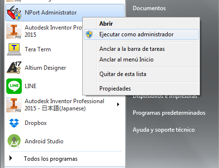
1. Run the NPort Administrator program with administrator privileges:
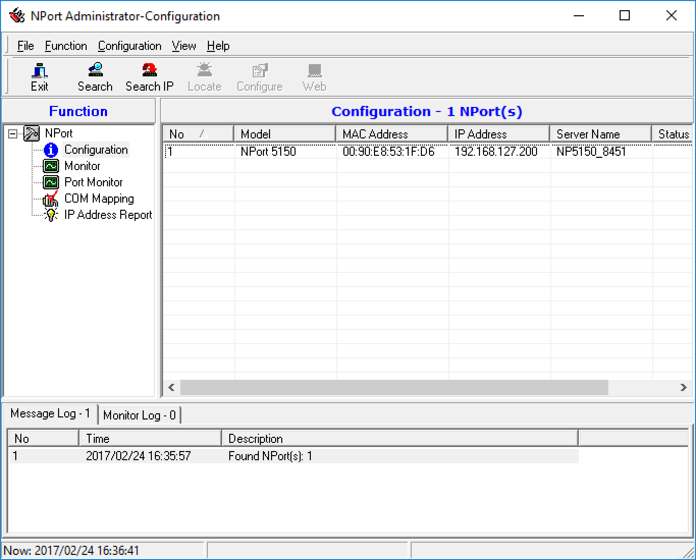
2. Press the Search button. The NPort 5151 should appear in the list with a generic IP address like 198.168.127.200.
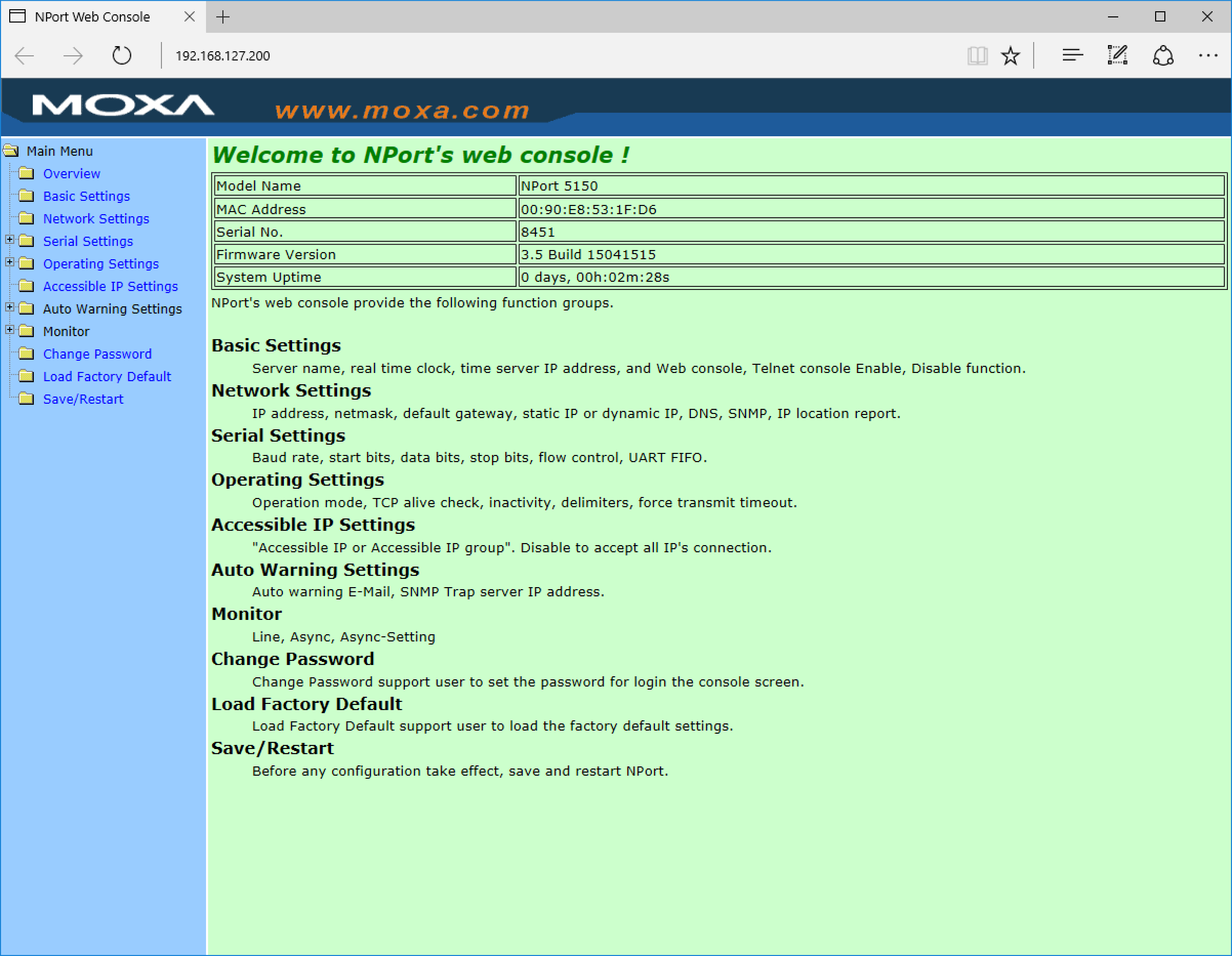
Note: Setting the IP number can be done either from the NPort Administrator program, or from the built-in web-server, by going to http://198.168.127.200 in a web browser. The following steps show how to do it from the NPort Administrator program and in the Appendix it is explained how to do the same in the web-server.
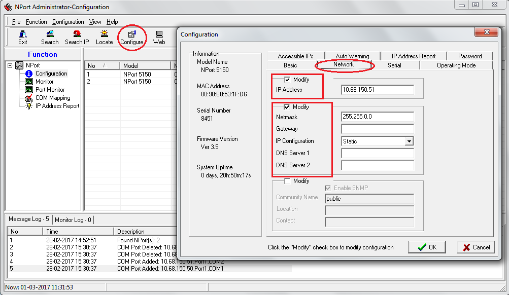
3. Select the connected device and press the Configure button. Click on Network Tab and click on Modify to change the IP Address, Netmask and others parameters acording to the table above.
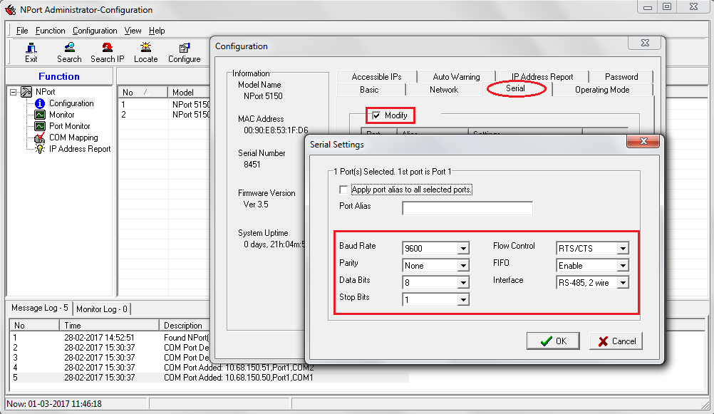
4. Click on Serial Tab and click on Modify and Settings to change the Baud Rate, Interface to RS-482-2-wire, and others parameters.
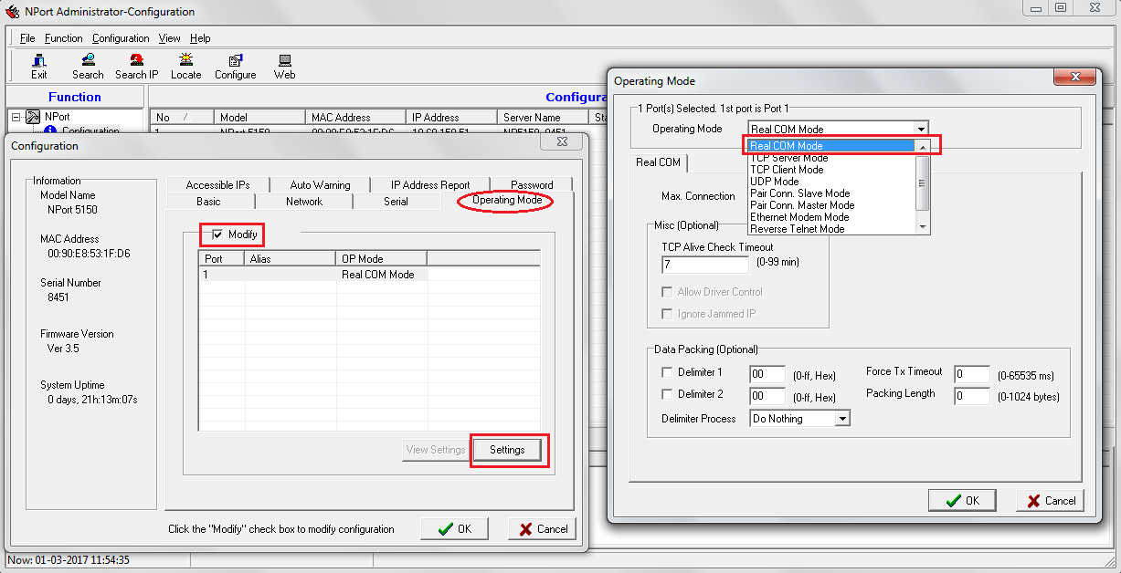
5. Click on Operating Mode Tab and click on Modify and Settings to select the Real COM mode.
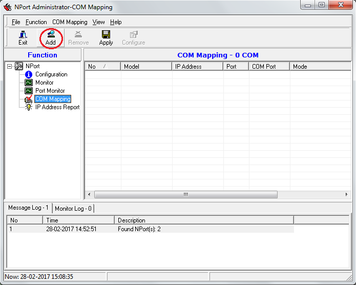
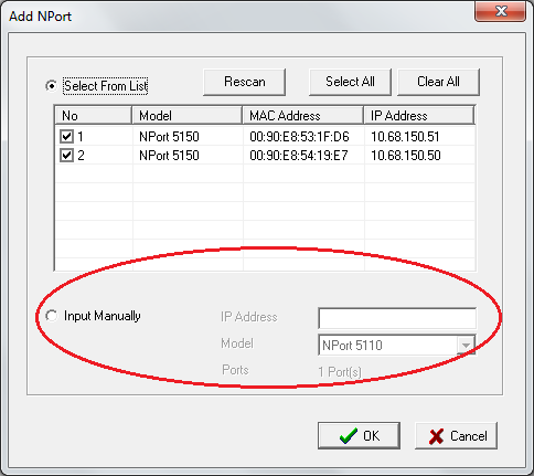
6. Go back to NPort Administrator and click on the COM Mapping. If there is no port in the list, click Add to add a port.
Note: You can also add the ports from the list or manually writing the IP address.
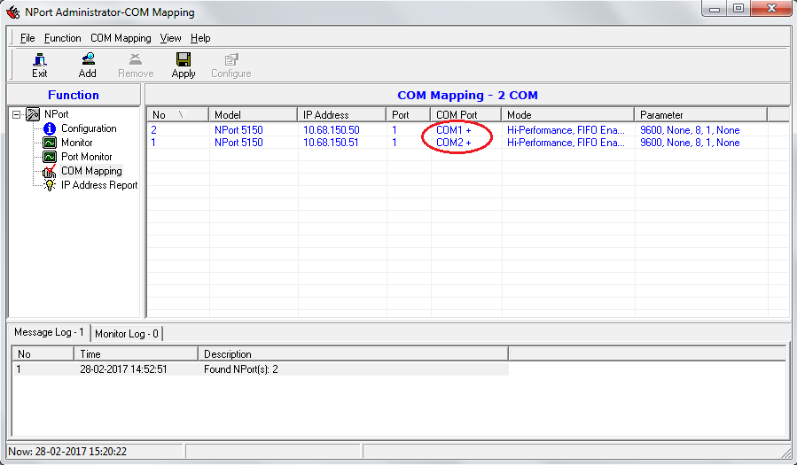
7. After selecting the port, the COM Port will appear with a “+” symbol and that means the changes have not been applied yet.
Note: After pressing the Apply button, the “+” symbol will disappear.
8. Start TMCL with administrator privileges.
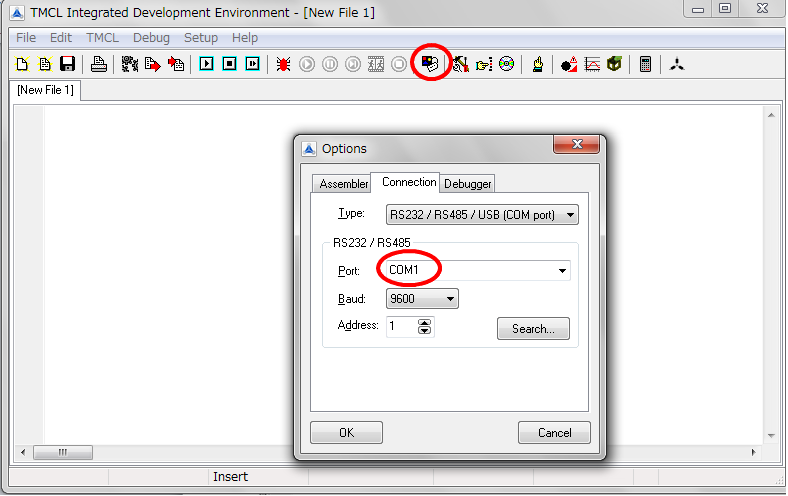
9. Select the Connection tab and set the same connection port that was selected before.
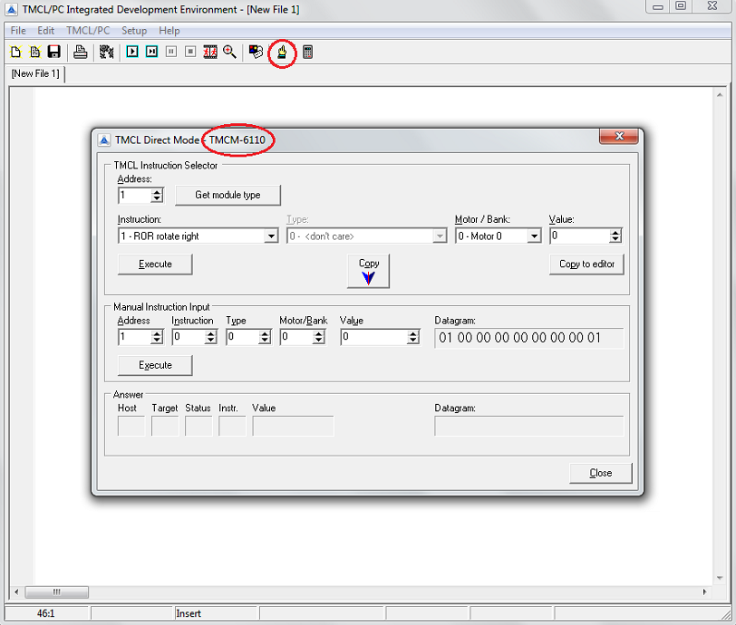
10. Click the Direct Mode icon and if the motor is connected the following window will appeard and the software will detect the module automatically (TMCM-6110 in this case). Then by selecting a command from here is possible to control the motor by executing the command.
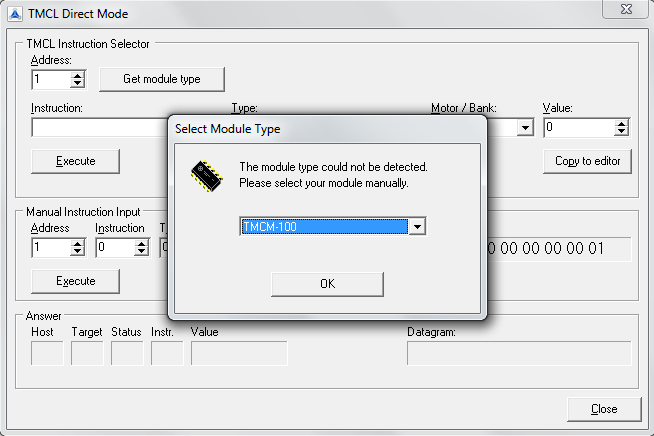
Note: If the motor is not connected or if the serial port has a different configuration the software will not be able to detect it automatically, so it will ask about the Module Type.
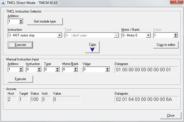
11. Select the instructions to move or to stop the motor.
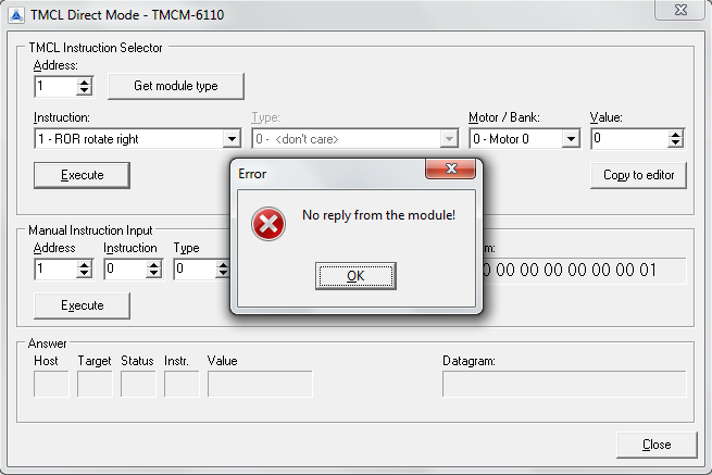
Note: If the motor is not connected the software will show the following window.
Appendix
Setting the parameters through the web-server:
i) Select the connected device and open the web browser. Please note that you can not make settings from the web browser unless you have administrator privileges:
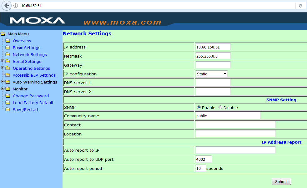
ii) Click on Network Settings to change the IP Address, Netmask and others parameters.
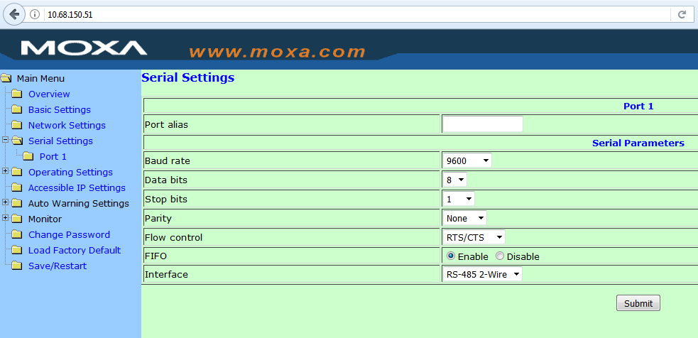
iii) Click on Serial Settings to change the Baud Rate, Interface to RS-482-2-wire, and others parameters.
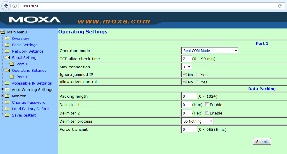
iv) Click on Serial Settings and select the Real COM mode.

