
|
Size: 65
Comment:
|
Size: 108012
Comment:
|
| Deletions are marked like this. | Additions are marked like this. |
| Line 1: | Line 1: |
| = Scraps of text for incorporation in the Vis Meeting Minutes = | = Scraps of text for incorporation in the VIS Meeting Minutes = [[KAGRA/Subgroups/VIS/MeetingNAOJ]] === Type-B === Albums * [[https://photos.app.goo.gl/YiRfy6a9uDf4rvcKA|BS remedying work after O3]] * [[https://photos.app.goo.gl/4cvWnXCdCsf9WiYf7|SR2 remedying work after O3]] * [[https://photos.app.goo.gl/X2eaBxsZGaRHYAQK6|SR3 remedying work after O3]] * [[https://photos.app.goo.gl/6C5tGpn7CLgGUG9y6|SRM remedying work after O3]] SR3 ballast mass adjustment highlights On top of Intermediate Mass * We recovered the oplev in order to use is as a reference for pitch. * '''Aim for the BF LVDT: 311 um per buoyancy correction'''. * After locking the IRM we checked the IM was free to move. * After we locked the payload and BF to the security structure, we removed the H1 OSEM flag and then the front and back panels of the IRM. * In two steps we removed a total of 100 grams from the IM and '''got the BF LVDT to 308 um at the temperature of the moment'''. * Once we finished the adjustment we assembled the IRM and put the OSEM flag back with magnet with the correct polarity. * '''Despite we used the oplev as a reference, apparently we disturbed the pitch by 496 urad approximately.''' This is should be within picomotor range. '''Yet to be adjusted.''' * '''We measured five IM transfer functions and the system looks very healthy.''' We didn't measure IM-V because the top filter is locked. On top of Bottom Filter (klog yet to be written) * '''F1 LVDT aim 416 um per buoyancy effect'''. * From IM ballast mass adjustment we calculated how much mass we require for the BF: 2 * 45 grams. * '''We quickly tested the calculation this morning with temporary ballast masses and got it to 412 um'''. * On Monday we will put the masses properly and fix them. === Type-B === Albums * [[https://photos.app.goo.gl/YiRfy6a9uDf4rvcKA|BS remedying work after O3]] * [[https://photos.app.goo.gl/4cvWnXCdCsf9WiYf7|SR2 remedying work after O3]] * [[https://photos.app.goo.gl/X2eaBxsZGaRHYAQK6|SR3 remedying work after O3]] * [[https://photos.app.goo.gl/6C5tGpn7CLgGUG9y6|SRM remedying work after O3]] SR3 alignment recovery ([[http://klog.icrr.u-tokyo.ac.jp/osl/?r=15928|klog15928]]) * We installed the oplev hardware, installed a new (orange) power cable for it and re-routed QPD cables underneath the floor panels. * We used the IP horizontal fishing rods to place the IP in the vicinity of the setpoint. * IM-Y had an unusually large value, namely, -2.9 mrad. I don't know how this happened and I should check. I used the picomotor to set it back to around zero. * Although we tried to keep the same value of yaw of the chain when we installed the F0 yaw motor, we might have change a little bit. * I tried to align the oplev without moving the components on the board, provided they had been aligned. However, the position of the collimator seems off by a large amount and a lot of adjustment in tip and tilt was necessary. * At the end of Thursday the beams were coming close to the QPDs but I think I need to move the position of the collimator. I'll do this on Monday. * The temperature was 23.1 degrees. Plan for next week * Monday: Finish the alignment of the oplev and move the BF fishing rod to midrange. * Tuesday onwards: begin the adjustment of the IM ballast mass. === Type-Bp === Albums * [[https://photos.app.goo.gl/WvmWMxPAsN6793ubA|PR3 Remedying Work]] PR3 Gluing of the mirror wire * Last week Friday we had mixed two portions of EP30 in order to test the adhesive. They both cured well so, on Monday we prepared another portion in a plastic tray and applied it to the wire. I have the impression that the problem with the portion that didn't cure was that we used an improvised tray with folded Al foil and the low viscosity component went in between folded Al sheets. * In Tuesday the new portion had cured so we proceeded to install the front ring and then released the payload. * '''According to the oplev, we disturbed the pitch by +3.8 mrad approximately''' ([[http://klog.icrr.u-tokyo.ac.jp/osl/?r=15941|klog15941]]). The value of pitch with respect to the horizontal still has to be measured, the mirror must be realigned to 1/300 rad with picomotors and the OSEMs adjusted. Traverser in PR3 and PR2 * Together with Ikeda-san we tested the Traverser driver. We set up dial gauges onto the motors to measure their motion. However, the traverser simply didn't work ([[http://klog.icrr.u-tokyo.ac.jp/osl/?r=15889|klog15889]] and comments). * Later on we learned that the connector pin assignment was different from PR2 and PRM, and that there was even an adapter connector for PR3. * Ikeda-san and Hirata-san tested the Traverser in PR2 using the dial gauges and it worked well ([[http://klog.icrr.u-tokyo.ac.jp/osl/?r=15930|klog15930]]), so the strategy became to change the pin assigment in the in-vacuum connectors. === ----------------------- === === General === [Fabian, Hirata] We inspected SR3 payload and chamber and came up with a plan for installing a thermistor. * There's a mechanical design already. * We have the thermistors already. * The plan is to install them in 7 suspensions. * Type-Bp chambers have unused connectors we can use for this application. * Show diagram of how this would look like in Type-B. The diagram for Type-Bp still has to be done. === Type-B === Albums * [[https://photos.app.goo.gl/YiRfy6a9uDf4rvcKA|BS remedying work after O3]] * [[https://photos.app.goo.gl/4cvWnXCdCsf9WiYf7|SR2 remedying work after O3]] * [[https://photos.app.goo.gl/X2eaBxsZGaRHYAQK6|SR3 remedying work after O3]] * [[https://photos.app.goo.gl/6C5tGpn7CLgGUG9y6|SRM remedying work after O3]] === Type-Bp === Albums * [[https://photos.app.goo.gl/WvmWMxPAsN6793ubA|PR3 Remedying Work]] PR3 * We checked the traverser cables. See klog report [[http://klog.icrr.u-tokyo.ac.jp/osl/?r=15836|15836]] * We identified cable R2 as the one failing. We used a multimeter to check for electrical continuity. In R1, T1 and T2 cables there was continuity between pins 1 and 9, and between pins 2 and 3. However, in R2 there was only continuity between pins 2 and 3. * We removed the in-vacuum cable and checked it with the multimete, but it was fine. We checked the motor also. * We realized then it was the in-air connector adapter the one failing. We borrowed one from another place and it worked well. See in [[https://photos.app.goo.gl/8YUZwoeYXWEWVF9A9|this picture]] a thread is broken in the adapter. * We should make more adapters and make sure the traverser works well. * Gluing of the wire. See klog [[http://klog.icrr.u-tokyo.ac.jp/osl/?r=15852|15851]]. * We set up an oplev using a laser level. * We locked the payload. In the case of the vertical bars locking the RM to the IM, we used only one out of two becuase a cable was in the way of a locking screw. * The screws in the front ring came out smothly. * We applied adhesive as shown in this [[https://photos.app.goo.gl/WkAY67h3rKdxrkuJ9|diagram]]. See pictures in the album. * However, it's been two days later and the adhesive hasn't cured asin previous times. * I checked the pictures and I used the correct proportions. We used an improvised UHV compatible Al tray. * We mixed again in order to test the adhesive and we will check on Monday: * We used a plastic Petri dish and a small baking Al tray provided by Tomasru-san. * The new mixtures look translucent, as expected from previous experience, but the one we used on Wednesday looks more transparent. * Maybe some of the component with low viscosity was trapped in the folds of the tray. * How should we proceed? Let us discuss. * Yet to do once we finish * Shake the suspension to check if the mirror changes pitch as before? * Measure the orientation of the mirror with respect to the horizontal with an oplev, using the IM picos set the pitch to 1/300 and adjust the OSEM if necessary. * Move the traverser while inspecting visually. == Type-B == Albums * [[https://photos.app.goo.gl/YiRfy6a9uDf4rvcKA|BS remedying work after O3]] * [[https://photos.app.goo.gl/4cvWnXCdCsf9WiYf7|SR2 remedying work after O3]] * [[https://photos.app.goo.gl/X2eaBxsZGaRHYAQK6|SR3 remedying work after O3]] * [[https://photos.app.goo.gl/6C5tGpn7CLgGUG9y6|SRM remedying work after O3]] Week of the 18th of January SRM I disconnected SRM picomotor drivers to move them away from the assembly frame. I failed to report it in a klogin due time. BS * Miyo-kun, Hirata-san and I reviewed the IP transformation matrices from IP LVDTs to L, T and Y and from actuation in L, T and Y to real coil-magnet actuator. We found a few of inconsistencies in existing documents. See klog reports [[http://klog.icrr.u-tokyo.ac.jp/osl/?r=15769|15769]] and [[http://klog.icrr.u-tokyo.ac.jp/osl/?r=15776|15776]]. * We recovered the IP alignment: * See klog [[http://klog.icrr.u-tokyo.ac.jp/osl/?r=15782|15782]]. * I updated the medm screen with these matrices. Diagonalization is pending. * I moved the IP close to the setpoint using horizontal FRs. * I turned the control system on by hand and works fine. (I tried using Guardian but it keeps using the old setpoint values despite I took a snapshot.) * I moved BF keystone to around zero. (F1 keystone has been in midrange for a long time and we should not move it unless it's absolutely necessary.) * We went to the tunnel and recovered the oplev readout. We had to move the suspension in yaw by a lot (mrad maybe) using the new F0-Y stepper motor. * After recovery I measured TFs in the IP. They look fine, but in IP-L and IP-T the coherence is low from 150 mHz to 400 mHz. Terrence suggested to check coherence with ground motion and we cna also increase the amount of actuation. * We finally got to add ballast mass on top of BF: * When we began working the temperature was 23.1 degrees but when we finished it was 23.5 degrees ([[http://klog.icrr.u-tokyo.ac.jp/osl/?r=15809|klog 15809]]), likely due to the coach filters ([[http://klog.icrr.u-tokyo.ac.jp/osl/?r=15810|klog 15810]]), but this morning it was 23.0 degrees. * The final result is that the keystone is now about 16 um above the goal. It requires -1,100 counts of coil-magnet actuation to reach it. After pump down we can use the FR to move it closer if we think it's suitable. * The aligmment of the OSEMs didn't change much. * IM TF measuements reveal that the system is healthy. * Things left to do in BS suspension: * In F0 adjust ballast mass, FR position and limit switch positions. * Tune IP resonant frequency. * Measure IP-LVDT sensitivity. * Install oplev box (what is the status?) * Install outer frame large beam? (what is the status?) Plan for next week SR3 * Alignment recovery after cabling (it seems they want to use it next week for injecting green light.) * Preparation for ballas mass adjustment. == Type-B == Albums * [[https://photos.app.goo.gl/YiRfy6a9uDf4rvcKA|BS remedying work after O3]] * [[https://photos.app.goo.gl/4cvWnXCdCsf9WiYf7|SR2 remedying work after O3]] * [[https://photos.app.goo.gl/X2eaBxsZGaRHYAQK6|SR3 remedying work after O3]] * [[https://photos.app.goo.gl/6C5tGpn7CLgGUG9y6|SRM remedying work after O3]] Week of the 11th of January BS: [[http://klog.icrr.u-tokyo.ac.jp/osl/?r=15729|klog 15729]] * We finished the cabling of the F0 yaw stepper motor. Ikeda-san updated the software with the channel number selected. * W tested F0-V and F0-Y limit switches by pressing them with the finger and checking the response in the medm screen. They worked as expected. * We checked the polarity of the IP coil-magnet actuators. H1 had the reverse polarity and it was corrected in hardware. * Using information collected before the removal of the LVDTs and after their installation and calibration, I calculated the offset to write in the medm screen in order to have the desired setpoint at zero (klog pending). * Hirata-san and Fabian updated the medm screen (klog pending). * The SDF table was updated with the new values (klog pending). * The next steps (to happen today or Monday) are * To write in the medm screen the simple geometrical transformation matrix from H_{i} to L, P and Y and * Turn the control system on and make sure it's stable. * Diagolalize the LVDTs and their actuators. SR3 We moved the SR3 small rack inside of the clean booth to a new permanent position.See this the location in [[https://photos.app.goo.gl/GtobbsRubsq6jEi89|this picture]] and [[https://photos.app.goo.gl/pDJ8PYTAEcTueMpY7|this other one]]. * The boxes with electronics were put following the same layout as in SR2 and BS, which was reported by Washimi-san in [[http://klog.icrr.u-tokyo.ac.jp/osl/?r=15736|klog 15736]]. * The cables were routed underneath the 2nd floor panels in a tidy way. * The connections still have to be tested by turning the control system on. I aim to do this next week. * The SRM cables and rack still have to be arranged in the same way. * Mirapro can move the rack at any time of their convenience, with the exception of Monday, when we will remove some items which are next to the assembly frame in the 2nd floor and next to the SR3 chamber in the 1st floor. Plan for next week * Monday: * Removing items around SRM and SR3 chambers to allow Mirapro work whenever is suitable for them. * Add ballast mass in BS BF. * Others: * Recover SR3 alignment after cabling as preparation for ballast mass adjustment (1 person). * Install SR3 oplev (2 people). * We should install it depite it would make access to the payload difficult. * This difficulty is mitigated by the fact that we have access from the side doors. We will assess this situation in situ and decide. * In case we decide not to install the usual oplev we will use an improvised oplev supported by the chest of drawers far away enough from the door to allow access. * Lower the pre-isolators with the jacks (3 people). * Adjust ballast mass on top filters. * Set the F0 limit switches in suitable positions. * Measure again resonance frequencies of IPs as preparation for adding mass onto them to adjust such the frequencies. == Type-B == Albums * [[https://photos.app.goo.gl/YiRfy6a9uDf4rvcKA|BS remedying work after O3]] * [[https://photos.app.goo.gl/4cvWnXCdCsf9WiYf7|SR2 remedying work after O3]] * [[https://photos.app.goo.gl/X2eaBxsZGaRHYAQK6|SR3 remedying work after O3]] * [[https://photos.app.goo.gl/6C5tGpn7CLgGUG9y6|SRM remedying work after O3]] Week of the 4th of January SR3 * In order to answer the question whether we should move the assembly frame next to SR3 as a back up plan, * We opened SRM chamber -X door, next to where the frame is now and * We measured the width of the clear space: 66 cm, which is enough. * We should ask Mirapro to move the frame, but * We need to move the rack with electronics and the cables and we need to allocate time to do it. * The IP stepper motor shaft pitch was measured to be 1.0 mm/thread. BS * The IP stepper motor shaft pitch was measured to be 0.8 mm/thread. * We received special screws, we installed the IP LVDTs and calibrated them: I have not checked the data but we might need to optimize the LVDT cards and repeat the calibration. I need to think about this issue more carefully. * Before removing IP immobilizing jig we measured the output of the LVDTs in order to recover the aligned position. * We replaced the heavy F0 top plate of the keystone assembly by a lighter one with ballast mass. * We installed the F0 yaw stepper motor with limit switches. Test pending. * We installed the F0 fishing rod limit switches. Test pending. Type-B all We checked the flanges we could use for the cables of a thermistor. See details in klog [[http://klog.icrr.u-tokyo.ac.jp/osl/?r=15700|15700]]. == Type-B == Albums * [[https://photos.app.goo.gl/YiRfy6a9uDf4rvcKA|BS remedying work after O3]] * [[https://photos.app.goo.gl/4cvWnXCdCsf9WiYf7|SR2 remedying work after O3]] * [[https://photos.app.goo.gl/X2eaBxsZGaRHYAQK6|SR3 remedying work after O3]] * [[https://photos.app.goo.gl/6C5tGpn7CLgGUG9y6|SRM remedying work after O3]] Week of the 14th of December * Yano-san repaired a damaged thread in a BS LVDT component. He also compiled the bill is screws. * Hirata-san and Yano-san went to wash the BS LVDT components ot the University of Toyama. * The components were brought back to the tunnel on Friday. * The plastic box was opened until Monday to let the components warm up to room temperature and thus avoid condensation. * Yano-san finished writing a nice [[https://1drv.ms/b/s!AoQaV1tdsEcUgdcAlrRYet7V9XqUFw?e=QNl8TV|procedure to assemble the LVDTs]]. * After receiving and washing new screws, we mounted the new lighter F0 keystone assembly top disc in SR3 (klog [[http://klog.icrr.u-tokyo.ac.jp/osl/?r=15664|15664]]). We removed 96 grams to compensate for the extra weight of the F0 yaw stepper motor mechanism. * I finished writing the procedue for adjustting ballas mass in SR3. Hirata-san and Yano-san read it and they had comments. * The temperature in BS area this week was still high (around 23.6 degrees). Yokozawa-san had misread my message and he thought such temperature was the one requested. Now he is aware of the temperature we want (close to 23.1 degrees). * Despite the temperature being high, we added ballast mass on top of BS BF in order to assess how easy or hard was going to be to keep the BF current balance (klog ''' [[http://klog.icrr.u-tokyo.ac.jp/osl/index.php?r=15651|15651]]''' and comments): * As planed, we put equal amounts of mass on geometrically opposite places: 66 grams in each place. * It worked well in the sense that we didn't disturb the aligmment of the IMR and OSEMs. The largest change was -41 urad in IM-R, which is rather small for this type of adjustment. * Transfer function measurements showed a healthy system. * F1 fishing rod had been put in mid-range beforehand and the additional ballast moved keystone position down by 560 um to 423 um. We will need to add more ballast later because we aim to 212 um. * The yaw measured by the oplev changed also, but this is due to the change in F1 height and coupling with cables. Week of the 21st of December * On Monday we receive the BS IP LVDT yokes: * They were cleaned during 5 minuted in the ultrasonic bath with acetone in ordert to remove residual rust, likely coming out from threaded holes. * We assembled completely two LVDT-actuator units; the other one was partially aseembled because we only have two jigs. After installing the first one we will finish the assemby of the third one. * After assembly we checked the resistances of the coils to make sure there was no damage. * We finished the assembly and installtion of the BS limit switches for the IP horizontal fishing rods. * We attached extensions to some of the cables. * Because of the lack of cable clamps in the designed we used inserted M8 vented SDC screws in nearby holes and used them as poles. We tied cables to them using kapton coated wire. * We tested the switches manually and checked the medm screen gave the correct signal. * In SRM we corrected the polarity of the F0 FR stepper motor. * There was some troubleshooting to do: a cable broke at the attachment point to a pin (pin 2) and we fixed it. * Using a spare stepper motor we checked the health of the unused channels in the SRM GAS Filter driver: two out of three work. == Type-B == Albums * [[https://photos.app.goo.gl/YiRfy6a9uDf4rvcKA|BS remedying work after O3]] * [[https://photos.app.goo.gl/4cvWnXCdCsf9WiYf7|SR2 remedying work after O3]] * [[https://photos.app.goo.gl/X2eaBxsZGaRHYAQK6|SR3 remedying work after O3]] * [[https://photos.app.goo.gl/6C5tGpn7CLgGUG9y6|SRM remedying work after O3]] Week of the 7th of December * We connected some SR2 and SRM cables which had been disconnected as preparation for the clean booth cleaning. * We BS IP immobilizing jig and LVDT-actuator units. * Some holes were out of place due to manufacturing imperfections but we were able to fix the component using only one screw. * Then we found another hole was also out of place. Hirata-san and Yano-san made additional holes and it worked very well. * After immobilizing the IP we removed the LVDTs and diassemebled them. * The LVDTs had oil, rust, dust, ink, small pieces of polystyrene foam, etc. * We wrote a rough procedure to use it as a guide to assemble them back, including cabling diagram. * Some of the think wires broke when removing the pins from the connectors, but Hirata-san crimpped new pins successfully. * We measured the resistances of the coils and determined the polarity of magnet arrangement. * The yokes were given to Takahashi-san who sent them to the company. We'll have them back by the 23rd of December. * On Tuesday and Wednesday Hirata-san and Yano-san will go to Toyama University to wash the components. * On Monday morning Yano-san will compile a bill of screws based on our notes. * The BS F0 stepper motor was assembled but not installed. We'll do it after recovering the IP LVDTs. * Two BS IP horizontal stepper motor limit switches were assembled. * One of them was put in place just for us to check iy fitted in place. It looked alright. * The assembly does not have cable clamps for the cables, but we thought of a plan. We only require to but additional screws. * In SR3 IP we wanted to replace a heavy disc in the F0 keystone assembly. However, the holes in the new piece have countersinks and current piece uses socket head screws. We will install it after buying new suitable screws. * Yano-san made some holes bigger in some ballast masses (from M5 to M6). * The temperature in BS area is currently 23.8 degrees. We want around 23 degrees. Hopefully next week we will be able to adjust the ballast mass in BS BF. * I began writing the new procedure to remove ballast mass from SR3 Im inside of the chamber. * No need to design new ballast masses or any other piece. * I aim to finish it shortly and I'll ask Hirata-san to check it. * I should be able to tell you how long it will take to do this some time next week. == Type-B == Week of the 30th of November General * Yano-san pointed out that the factory cables for the stepper motors are thick (for higher current) whereas we are connecting them to thin cables. We need to check whether this may be a problem. BS * We inspected the IP LVDT-actuator units and horizontal fishing rods. See pictures in [[https://photos.app.goo.gl/YiRfy6a9uDf4rvcKA|this album]]. * The yokes have some rust and coils have dust. * The horizontal FR blades don't have nickel plating but they are not rusty in an obvious way. * We found the jigs to remove the LVDTs. * We checked there's suitable access to install Satou-san's limit switches. * Terrence did various measurements and we locked and unlock the IP for it. * Temperature in the clean booth is high (24.7 degrees). I kindly asked Yokozawa-san to take action to cool it down. SRM, SR3 and SR2 * We finished the installation of the F0 FR limit switches after we got new fasteners. * In SRM and SR2 we compensated the additional mass of the yaw stepper motor assemblyby removing ballast mass from the keystone. * In SR3 we set the F0 FR upper limit switch to a suitable height. * We tested the switches by pressing them manually and checking the signal in the medm screen using the update button. They worked fine this way. * However, some of the Nikhef switches in the IPs require fixing. They are made of copper sheet and they are bent in such a way that system receives a trigger signal even when they are not pressed. The cales are fine because they react when they are pushed by hand. * SR2: H1, -Yaw, Left; H2, -Yaw, Left. * SR3: H1, -Yaw, Left. * SRM: We fixed one. * Tthe script doesn't automatically warns the human user when a switch has been pressed. Currently, the update button has to be pressed to know the status. Ikeda-san will implement an automatic warning by the end of January. * Ikeda-san clarified the driver should stop the motor as soon as the switch is pressed. We did an experiment that is shown in [[https://photos.app.goo.gl/f88KYATJwHNZpFHw8|this short movie (SR3)]]. * In SR3 we connected again the satellite boxes to the rack. A TO DO list for SR suspensions. * Fix the IP limits switches which are not working. * Recover the local alignment of the suspensions and measure transfer functions.''' ''' * Change polarity of SRM F0 FR stepper motor. * In SR3 exchange the heavy top plate (1 kg) from the keystone assembly by a lighter new one (less than 400 g). * Set all the switches to suitable positions. * Make sure the script automatically detects the pressing of the switches. * Repair connector adapter for picomotors. Check whether there are missing ones. * Connect BF picomotors in BS and SR3. * SRM IM-R picomotor is not working. Check it. * Decide what to do about the position of the F0 keystones: they are very low because we lifted the suspensions with the jacks in order to compensate for the buoyancy effect. However, Mark made us change our minds and we didn't lowered them back before O3GK. == Type-B == Week of the 23rd of November 2020 [Hirata, Washimi, Satou, Aso, Fabian] SRM * On Tuesday morning we realized '''it was a lock nut that was too low the one causing the problem'''. See klog [[http://klog.icrr.u-tokyo.ac.jp/osl/?r=15518|15518]]. * In the morning I moved the three nuts and the keystone moved down to about -1.2 mm. * In the afternoon Hirata-san moved the nuts further up but the keystone didn't reach go beyond -1.2 mm. * I checked the 3D-CAD and realized the OSEM flag and body impose a limit of ± 1.75 mm when the IM-IRM and OSEMs are perfectly aligned. In SR3 the limit is -1.470 mm. * This sugguests -1.2 mm is the limit and it's determined by the overall alignment of the system. We should check where the limit is in SR2 and BS also. * Health check of SRM payload is pending. * The 30 mHz oscillation I talked about in last week's meeting is aliasing noise. * I was looking at a slow channel that down-samples data from a fast channel, and the fast channel has high frequency noise (~250 Hz). * This type of high frequency noise had already been noted by Type-A team and we had put low-pass filters in an inout fiter bank to avoid it. However, the filter had been turned off some time ago and the noise became obivous. * A particular feature of the noise is that it's amplitude seems to depend on the position of the keystone. * In klog [[http://klog.icrr.u-tokyo.ac.jp/osl/?r=15305|15305]] I showed the amplitude incresed when the keytone goes down. However, on Tuesday we saw the opposite. '''More analysis pending.''' * When we began the installation of F0 fishing rod limit swtiches we realized some holes that were expected to be fully threaded were not threaded at the top. We quickly came up wit an additional plan and additional components have been ordered already. We'll finish installation next week. * We tested the polarity of thr F0 FR motor. We got the opposite I had reported in klog [[http://klog.icrr.u-tokyo.ac.jp/osl/?r=15272|15272]]. The reason is that in the script Ikeda-san had put a minus sign. '''It was agreed to remove the sign and change the polarity in hardware: we want the keystone to move up with a positive number of steps'''.''' This convention is alright, although the oppsite is common in motors we cannot access.''' * Satou-san realized he had made a mistake in the cabling diagram of the F0 yaw stepper motor (klog [[http://klog.icrr.u-tokyo.ac.jp/osl/?r=15530|15530]]).''' He quickly notified us and we will correct this error when we open the camber next week. '''(We did the one in SR3 correctly, klog [[http://klog.icrr.u-tokyo.ac.jp/osl/?r=15541|15441]].) * We removed 108 grams from the F0 keystone to compensate for the addiitonal mass of the limit switch components (~100 grams). * Question for Ikeda-san and Aso-san: was it possible to test Ikeda-san's script to unjam F1 FR motor? * Collateral damage: the fibre optic camera is not working. We tried to use it on Tuesday afternoon but it just keeps saying it's "Establishing connection". SR3 * We installed the limit switches in F0 FR and F0 yaw stepper motor and tested them using the medm. See klog [[http://klog.icrr.u-tokyo.ac.jp/osl/?r=15541|15441]]. * We new F0 yaw stepper motor asembly is roughly 100 grams heavier, and the keystone doesn't have ballast mass on top to remove, so the load is heavier now. Later we will replace the top disc (1 kg) by a new lighter one. * We had to remove some IP arch ballast masses to relocate a misplaced connector onto the IP table to allow us to connect the limit switches. We rearranged some cables also. == Type-B == [Hirata-san, Washmi-san and Satou-san, Ikeda-san, Fabian] General * They assembled BS F0 yaw stepper motor and SR limit switches. * They Removed screws from SR3 chamber top and side doors. * They did cable inventory. * Ikeda-san finished the script to actuate on the jammed stepper motor. * We checked IP limit switches using the medm screen and physically pushing them with an Allen key. They worked well although they are very stiff. One of them experienced a plastic deformation and had to be bent back. Satou-san system seems to be better. Klog [[http://klog.icrr.u-tokyo.ac.jp/osl/?r=15484|15484]]. * After Yokozawa-san's actions the temperature became 23 degrees, which is suitable. * On Friday I tried to moving the jammed stepper motor when applying a large actuation on the keystone, both ways. It didn't solve the problem. Klog [[http://klog.icrr.u-tokyo.ac.jp/osl/?r=15479|15479]]. SR3 * After working this week inside of SRM chamber, we have the impression we may be able to add weight to the SR3 BF without taking it out of the chamber and, at the same time, do it in a suitable way to keep the IRM alignment. * To add mass to the IM we would require removing only two IRM panels and one OSEM. * Next week we can inspect the BF and find whether it's possible or not. SRM trouble mechanical troubleshooting * On Monday I recovered the alignment before in situ inspection in the mine. Klog [[http://klog.icrr.u-tokyo.ac.jp/osl/?r=15474|15474]]. * General visual inspection: everything looked fine, including cables. Klog [[http://klog.icrr.u-tokyo.ac.jp/osl/?r=15474|15474]]. * Although no cable seemed to be causing problems, for the sake of trying we unclamped from the Flying Saucer the only real suspect cable, which is the picomotor kapton cable. We measured a transfer function and the problem was still there. Klog [[http://klog.icrr.u-tokyo.ac.jp/osl/?r=15474|15474]]. * We looked to the inside of the BF with the camera: it did not produce useful images. Klog [[http://klog.icrr.u-tokyo.ac.jp/osl/?r=15477|15477]]. Pictures at [[https://photos.app.goo.gl/6C5tGpn7CLgGUG9y6|SRM Remedying Work after O3GK]]. * We tried all the suitable holes at the bottom and at the top (keystone lock screws and nuts access). * Once inside the BF, we cannot point the camera where we want. Mostly we only saw the cap and sometimes the keystone. * We were able to identify some components but it's still too dark. We need more light. * We inspected visually the bottom central section of the BF, which is the coil-magnet actuator assembly. Nothing seemed wrong. * The three of us (one at the time) pulled the suspension rod down by hand, and it moved by several milimeters smoothly. It didn't feel like rubbing anything. Klog [[http://klog.icrr.u-tokyo.ac.jp/osl/?r=15485|15485]]. * Assessment of SRM from the control room: see this [[https://1drv.ms/b/s!AoQaV1tdsEcUgdMYn2O7DcFhmPGU5Q?e=wFmIH1|presentation]]. Netx two weeks plan * According to the Microsoft Project: * Next week is for limit switches in SR2 and * The week after the next is for "adjustment of ballast mass in SR3", which is separate a separate item from "Repair removing suspension". They are actually the same. * For the next two weeks we can: * Install the limit switches in all suspensions (F0 yaw and vertical). * Look for accessible places where we could add mass on SR3 BF from within the chamber and write a procedure. * Fabian still has to design some simple ballast masses for SR3 IM. * Aso-san can take a fresh look to SRM payload if he wants. == Notes for SRM Klog on 19-11-2020 == === Assessment of BF and IM === Conclusion * The BF and IM in vertical both behave very well for displacements high above zero, for example at 288 um. The transfer functions look fine. * When BF keystone is at 172 um, a 30 mHz oscillation appears in BF LVDT but, strangely, not in IM-V. The transfer functions look fine. * When BF keystone reaches 132 um (and IM-V is 185 um), IM-V stops and seems to be dragging. With the exception of IM-V, all IM transfer functions look fine. BF LVDT shows the oscillation at 30 mHz. Conditions * Temperature: 23 degrees. * F1 at -567 um (no actuation). Description of experiments 1. The BF keystone is at 288 um and the IM-V at 321 um. * The BF transfer function looks very good (picture 1p1). * The IM-V transfer function looks also good (picture 1p2). The vertical OSEMs don't seem to be out of range although they might be close to their limit. I need to check. * The IM-Y transfer function also looks good (picture 1p3). * When it swings free there is no large oscillation (picture 1p4). 1. BF keystone down to 172 um (-2000 cnt of actuation). * A large oscillation appears: 8 um-pp at 30 mHz. See 2p2. * The BF transfer function looks very good (picture 2p3).The resonant frequency is at 273 mHz. * The IM-V transfer function looks also good (picture 2p4). 1. I moved the BF keystone down to 132 um with -2800 cnt of actuation. IM-V goes down to 185 um. * BF oscillates with an amplitude of 9 um-pp at about 30 mHz, but IM-V does not move! See picture 3p1. * Then I applied a sinusoidal actuation with an amplitude of 2000 counts at 100 mHz. See picture 3p2, 3p3. I removed the AC actuation and measured transfer functions. * IM-Y and IM-L transfer functions looks fine. See 3p4, 3p5. * IM-P looks good. See 3p6. * IM-R looks good although noisy at high frequencies. See 3p7. * IM-V looks really bad. See 3p8. 1. Then I set the DC actuation to -2000 counts and turned the AC actuation on. The IM vertical OSEMs seem to be completely free from any stop and follow the actuation. Pictures 4p1, 4p2, 4p3. The BF follows the actuation also. 1. I removed the sinusoidal actuation completely and kept the AC one. The BF oscillates with a very low frequency again. See 5p1, 5p2. 1. I removed the DC actuation completely. The low frequency oscillation in BF is gone. See 6p1. === Assessment of F1 === Conclusions It seems that when the keystone is placed around zero (original nominal) and above, a coupling with other mechanical elements appear. This manifests itself as persistent oscillation above 310 mHz, the decrease in the height of a peak in transfer functions, change in its frequency and a decrease of coherence below such a frequency. '''The system seems to be free of stray couplings at -572 um or below.''' However, a clear boundary between healthy and unhealthy behaviour has not been established yet. Conditions * Temperature 23 degrees. * BF keystone position 280 um. Desription of measurements 1. I left F1 keystone at -182 um (10,000 counts of actuation) free swinging last night and, despite the time elapsed, the oscillation at 312.5 mHz has not damped (picture 1p1, 1p2). It has an amplitude of 30 um-pp. I assume it continues because the excitation hasn't ceased. '''The transfer function looks very good (1p3)''' but the resonant frequency is at 273 mHz not at 312.5 mHz. 1. I removed the actuation and the keystone goes down to -572 um. The large oscillation at 312.5 mHz is gone; we see the highest peak at the resonant frequency of 281 mHz (pictures 2p1, 2p2, 1p3). '''The transfer function looks very good.''' The peak shows up at 273 mHz not at 281 mHz (picture 2p4). 1. I turned the actuation on again (10,000 counts, keystone at around -182 um). The large oscillation is back, this time at 304 mHz, together with other oscillations in that frequency neighborhood (pictures 3p1 and 3p2). Then I turned the control system on, damping only, but it didn't damp it. I increased the gain but it became unstable. I don't have the TF in Foton to check the UGF and gain, so I gave up damping it. 1. I increased the actuation to 14,400 counts to bring the keystone around zero. The oscillation is still there (pictures 4p1, 4p2) and it appears in a slightly higher frequency, at 328 mHz. '''The transfer function shows an unhealthy system''': the peak around 280 mHz is gone and a shorter peak appears at 304 mHz instead (picture 4p3). The coherence at that frequency is also high for a resonance (0.91).The coherence at low frequencies does not look as good. 1. I increased the actuation to 25,000 counts, which brought the keystone to around 450 um. The large oscillation is there (pictures 4p1, 4p2) at 320 mHz. '''The transfer function shows again an unhealthy system with the resonance at 320 mHz and with lower coherence below the first resonance (picture 5p3). ''' === Klog for 16-11-2020 === With Hiarata-san and Washimi-san. Preparation from the control room * Using the IM picomotors I changed the IM-Y from around -3,000 urad to around zero. * Using the Fishing Rod I moved F0 keystone from around -1,900 um to around -1,600 um (nominal). * Using 20,000 counts of coil magnet actuator I set the F1 keystone a reasonable distance from -100 um (nominal). The FR is jammed. * Using the FR I set the BF to around +100 (nominal). * I measured transfer functions of the IM. As before, all of the are alright except IM-V one. * The difference is that now, the IM-V TF measurement fails even when having the BF at 100 um. This is a very bad situation. In situ preparation * Hirata-san opened the vacuum chamber top. We covered the contact surface of the cap at the rim with the usual white tape. * We locked the IP and closed the chamber. * We opened the +X side door and also covered the contact surface at rim with white tape. Work inside the chamber * Hirata-san and I went inside the chamber and locked the IP. * We did visual inspection of the payload and of the visible part of the BF. Everything looked fine. * Still, I wanted to check whether the problem is produced by a cable. So, we locked the IM and IRM to the security structure and, at the Flying Saucer above the IM, we unclamped the kapton cable of the IM picomotors. One of the two M4 screws was completely removed. This was the most likely offender. * We measured the BF transfer function and it revealed an unhealthy system, which means this kapton cable is not the problem. We have not clamped the cable back yet * The white OSEM cables also look fine. It does not seem worth unclamping them to check. * Tomorrow we aim to check the inside of the BF with the fibre optic camera. === Type-B === With Washimi-san. * We inspected the BS BF in order to decide the size of a SDC M6 screw to buy. Hirata-san ordered a few (klog [[http://klog.icrr.u-tokyo.ac.jp/osl/?r=15435|15435]]). * We connected the cables for the SRM OSEM and the IM picomotors. An adapter for the IM picos broke and I borrowed from SR3 for now. * As preparation we turned on the optic fibre camera and realized it's missing a microSD card. Takahashi-san ordered one already. * I reported to Yokozawa-san that the temperature in SRM was about 21.8 degrees Celsius. We need it warmer next week. * SRM new problem: F1 fishig rod jammed at the lower end of its range. * Other FRs don't jam when reaching the end of ther ranges, but others do. * The expeced position of the keystone at 23 degrees in vacuum is -980 um (klog [[http://klog.icrr.u-tokyo.ac.jp/osl/?r=15461|15461]]), which is likely too large to bring the keystone to zero with the coil-magnet actuator. * What to do? Following our current line of thought, we should remove mass from the BF. Another option would be: * Hope fo the best next week and fix the BF. * Leave the SF wherever it lands (-1,037 um presumably), * Set the BF at zero and * Compensate the height of the mirror with at the F0 keystone or the IP jacks (better). === Type-Bp === With Washimi-san * After Shimode-san fixed a minor problem with one of PR2 LVDT drivers, we installed it back and it worked! * We measured the phases again. The results of almost all LVDT drivers used in PR suspensions are reported in klog [[http://klog.icrr.u-tokyo.ac.jp/osl/?r=15457|15457]]. * PRM BF recoil mass LVDT cards have not been examined because we need the problem with the misconnected cables solved. * One resistance in PRM SF GAS LVDT channel seems anomalous: it's value is only 1.2 Ohm whereas typical values are larger than 5 kOhm. === General === ==== About LVDT cards ==== [Fabian and Washim-san] With the new information that Alessadro (Nikhef) provided a few weeks ago, we began measuring the settings in PR suspensions. * I realized that the some of the information given to us ([[https://gwdoc.icrr.u-tokyo.ac.jp/cgi-bin/private/DocDB/ShowDocument?docid=4798|JGW-T1604798]], Feb 2016) about how to set up the card ready for calibration was '''wrong'''. * '''Namely, in order to set the phase, it is instructed to use the wrong probe points.''' * I wrote Alessandro for confirmation and he provided the correct information. * The consequences for the already calibrated LVDTs are not necessarly so important: * As far as I remember, the people adjusted the phase by maximizing the output, not by measuring the phase directly. * Still, from the recent measurements, I can see that some phases are very different from zero, which means we are not having the best SNR we can get from the LVDTs. * The consequences for LVDT card recovery are more important because, in case a card needs to be replaced, we have to get the same settings in order to preserve the calibration factor. * In case a card, whose settings have not been measured, breaks, we should: * Measure the value of two gain resistors from the top of the card and * Measure the value of one resistor from the '''bottom''' of the card. This requires removing the card from the chassis. === Type-B === [Fabian and Washimi-san] * I got the reviewer's comment on the Type-B paper. It's a long list but many of them are relatively simple. A few of them are a little more challenging. * We began setting up the clean booth ready for work. We also had had a chat about safety and how to keep the cleanliness. * We removed most of the screws from the top of BS and SRM chamber and from the +X side door of SRM chamber. * Akutsu-san and Nakamura-san inspected the BS oplev area with the intention of designing the box. * Mirapro covered the BS/PR2 area with SUS sheets. === Type-Bp === [Fabian and Washimi-san] * We measured the settings of PR2, PR3 and PRM GAS Filters LVDT cards: two resistances and a phase for each channel. * We'll check the remaining LVDT card in PRM once the cable problem is solved. * About: the LVDT driver box for PR2 GAS filters: * It has a problem with the input power voltage, but it may be just an LED issue because the meaured voltage seems alright. Shimode-san will check on Tuesday. * However, I didn't get a return signal from the BF-V LVDTs back into the board. The board might have broken. After Shimode-san finishes checking the power issue I'll investigate more. === Type-B === [Fabian] * I watched Mirapro removed the bellows and ducts, especially around BS, wich still has its oplev. Everything seemed alright. Let us measure TFs once the DGS is recovered. * Hirata-san picked up some components, which we will use in vacuum, in order to wash them in Mitaka. * Venting finished on Monday. The buoyancy effect on keystones was reported in klog [[http://klog.icrr.u-tokyo.ac.jp/osl/?r=15322|15322]]. This is very useful information for BS and SR3 work. * Once Mirapro removed the hatch doors in BS chamber that are at the BF level, I took a look and identified places to put the ballast masses. See klog [[http://klog.icrr.u-tokyo.ac.jp/osl/?r=15353|15353]]. Possible activities for the next weeks (subject to Takahashi-san's approval): * Removing clamps from the vacuum chambers caps. Mirapro will not do it. * Recovery of oplevs. * Measurement of gain resistances and phases in LVDT cards. * On BS BF filter, some ballast masses are fastened with a very long screw. Because we will add mass there, it would be good to estimate the length of the screw for preparation. In order to place a ruler next to it safely, it would be good to open the chamber and lock the IP, together with the BF cap. === Type B === Report for the week of the 19th of October 2020. [Fabian] * On Saturday Miyo-kun, Washimi-san and Fabian went to the tunnel and rerouted and reconnected cables in SR suspensions (IP and GAS LVDTs and FRs). We also reconnected the coil cables in BS OSEM satellite boxes for Guardian test. * Fabian confirmed the cabling was fine by using the fishng rods and monitoring motion with the LVDTs. I wrote the polarity down for Ikeda-san to use. See klog [[http://klog.icrr.u-tokyo.ac.jp/osl/?r=15272|15272]]. * Miyo-kun confirmed the new Guardian works for BS suspension. See klog [[http://klog.icrr.u-tokyo.ac.jp/osl/?r=15276|15276]]. * Hirata-san and I gave some feedback to Matteo about how we helped Hirose-san with the cleanliness of the mirrors before O3GK. * In the context of Ikeda-san's work with stepper motor scripts, together with Miyo-kun I revisited the IP fishing rods transformation matrices. * Before venting of the central room Fabian set the IPs and GAS filters in suitable positions (various klog reports). In the case of GAS filters it's useful to measure the keystone displacement due to bouyancy. * I checked SRM BF condition on Wednesday before the venting. See klog [[http://klog.icrr.u-tokyo.ac.jp/osl/?r=15305|15305]]. In previous analysis, it seemed the keystone hit a hard physical stop because it stopped moving when lowered. However, '''on Wednesday it didn't stop moving, but an oscillation at 40 mHz appeared. Currently I especulate it's a cable pulling.''' * I monitored the Type-B suspensions during venting. See klog [[http://klog.icrr.u-tokyo.ac.jp/osl/?r=15307|15307]]. I'll report the size of the bouyancy correction next week. * I wrote a To DO list for next week in Github: [[https://github.com/gw-vis/kagra-vis/issues/85|Type-B TODO list]]. === General === * [Fabian] During blackout preparation I realized Type-Bp suspensions use amplitudes of LVDT reference signals different to Type-B (5 Vpp). is the following information correct: * PR2: 6 Vpp. (This is written in a label, so I guess it's confirmed.) * PR3 and PRM: 7 Vpp. === Type B === Report of the week of the 12th of October * I gave some feedback for the noise budget paper. * We continued with the cleaning. * Hirata-san made M6 holes in some ballast masses. * I wrote a document about the procedure to replace the LVDT cards after a failure: [[https://gwdoc.icrr.u-tokyo.ac.jp/cgi-bin/private/DocDB/ShowDocument?docid=12128|JGW-T2012128]]. * It was checked by Alessandro Betolini from Nikhef and he says the method is correct. He provided minor comments that have been incorported to the new version of the document. * He says they will review the design for ETpathfinder and that's our chance to give them feedback (i.e. Tanaka-san's findings and my concerns as a user). * Knowledge transfer from Tanaka-san to Alessandro would be greatly beneficial for KAGRA. If you think it's suitable, would it be possible for someone to organize this, please? * Tanaka-san will take some of our LVDT cards for hardware modification. * We need to survey those LVDT cards before he takes them away. '''When will we do this?''' * As far as I understand, given the old calibration factor, he has to give us a procedure to calculate a new calibration factor. '''Is this statement correct?''' * Before any other card breaks, we need to survey all of them. '''When will we do this?''' * Four hands are required for the measurements. '''For Type-B/Bp, Washimi-san and Fabian can do it'''. * After cleaning the PR area I have the impression '''we lost Hirose-san's LED lamps''' to check mirror cleanliness. * I requested to buy a scale for Type-B work. === Type B === Report of the week of the 28th of Septermber * Measured the resonant frequency of BS IP ([[http://klog.icrr.u-tokyo.ac.jp/osl/?r=15136|15136]]). it's not too different to what I had measured with a higher temperature. I haven't measured the other ones. * I calculated we require to put '''132 grams on''' top of BS Bottom Filter in order to bring F1 to nominal position at zero with the fishing rod in midrange. See [[https://onedrive.live.com/?authkey=!AOLVVVKJ_Zpn-2c&cid=1447B05D5B571A84&id=1447B05D5B571A84!26691&parId=1447B05D5B571A84!26683&o=OneUp|Type-B remedying work]] document. * Taking into account the weight of the F0 yaw stepper motor (330 grams) that we need to install, and the amount of ballast on F0 keystone (413 grams), we can see the F0 load is overweight by 50 grams. * To fix this, Hirata-san designed a new F0 keystone top plate far ligher than the current one ([[https://gwdoc.icrr.u-tokyo.ac.jp/cgi-bin/private/DocDB/ShowDocument?docid=12090|JGW-T2012090]]). It should work well. * Next week I will go to the mine and put aside the 132 grams of ballast divided into two equal parts. * In the context of calculating the amount of ballast required in SR3 I realized that when moving the BF keystone to -1.47mm the system touches something and free oscillations stop ([[http://klog.icrr.u-tokyo.ac.jp/osl/?r=15122|15122]]). This is not a problem currently but it should not happen. More investigation is required. '''It touches before the fishng rod reaches midrange.''' * Despite this problem it was able to roughly estimate we require to '''remove 76 grams''' from the IM and '''add 43 grams''' on top of the BF. See [[https://onedrive.live.com/?authkey=!AOLVVVKJ_Zpn-2c&cid=1447B05D5B571A84&id=1447B05D5B571A84!26691&parId=1447B05D5B571A84!26683&o=OneUp|Type-B remedying work]] document. * I calibrated (roughly) the keystone displacement in terms of stepper motor steps, and then calculated the total displacement all the way to midrange position, which is beyond the position where it currently touches. Using the spring constant I calculated we need to remove 76 grams. * F1 fishing rod is completely jammed -429 um.To bring it to nominal we need to remove 33 grams from its load. However, we will remove about 76 grams from the IM, which implies we'll need to '''add''' 43 grams on top of BF. * We have a record of the mass we put on top of SR3 IM ([[https://onedrive.live.com/?authkey=!AOLVVVKJ_Zpn-2c&cid=1447B05D5B571A84&id=1447B05D5B571A84!26691&parId=1447B05D5B571A84!26683&o=OneUp|Type-B remedying work]]) and it seems hard to remove 76 grams in a symmetrical way. I'll need to design some masses that should allow us flexibility. Work in progress. * I opened a GitHub issue for concrete weekly TO DO lists ([[https://github.com/gw-vis/kagra-vis/issues/85|Type-B work TO DO list #85]]). I assigned Hirata-san, Washimi-san and myself. === Type B === Report for the week of the 7th of September 2020. * I finished the corrections of the Type-B paper. Mark is checking the final vesion and I will submit as soon as he is finished. * Miyo-kun, Ikeda-san and I went to the mine and did ballast mass inventory ([[http://klog.icrr.u-tokyo.ac.jp/osl/?r=14998|14998]]): * Fabian is in the process of checking roghly how much we will need. * We checked for rectangular ones for the top of IM, round ones for the top of BF and arch weights for IPs. * Pictures and the actual inventory are in a new album in Google Photos: [[https://photos.app.goo.gl/X2eaBxsZGaRHYAQK6|SR3 Remedying work after O3]]. * Pictures of the top of SR3 IM: [[https://photos.app.goo.gl/4XPFZhT1i8yNoTSQ9|IM_top_1]], [[https://photos.app.goo.gl/zCaGhGh3521xT9cw7|IM_top_2]], [[https://photos.app.goo.gl/KphJBYRTfdi65Szf7|IM_top_3]], [[https://photos.app.goo.gl/WQvYbXj3a7iXhPtq8|IM_top_4]], [[https://photos.app.goo.gl/JP95jUx5yVMh7uyF6|IM_top_5]], [[https://photos.app.goo.gl/Mm9vypUDD3oASgiV7|IM_top_6]]. We will likely need to replace thick ones by thinner ones with the same weight and then remove from opposite corners. * In the procedure document I wrote that we must measure the bouyancy displacement effect when we to the venting. '''Importanrt for the adjustment of the ballast masses in BS and SR3'''. * Before we did the pumping down with the contro on, so we only know the change in feedback signal. (I should use TF vales to calcilaye displacement.) * We should do it with the control off just to measure the displacement directly. * For SR3 and SRM I measured the resonant frequencies of IPs (klog [[http://klog.icrr.u-tokyo.ac.jp/osl/?r=15013|15013]]). * SRM IP looks fine. * SR3 IP requires adjustment, the resonant frequencies are relatively high and there's a large assymetry between L and T. We have very small arch weights to fix the assymetry. '''What's the TAMS300 experience?''' * I tried to assess the consequence of having ferromagnetic connectors close to magnets on top of SF (klog [[http://klog.icrr.u-tokyo.ac.jp/osl/?r=15011|15011]]): inconclusive results. * I haven't checked Sato-san's cable alternative proposal. === Type B === Report for the week of the 27th of April 2020. In the context of the Type-B paper I checked the noise level of the gephones: I did a calculation of the expected sensitivity and campared with Fujii-kun's measurements: * The calculation is based on Mathieu Blom's reported in his PhD thesis (Nikhef). In case you check it please be aware there are two typos in Eq. 5.10. * It includes the thermal noise of the pick-coil resistance, geophone suspension thermal noise and pre-amplifier noise. See this plot. The pre-amplifier noise is dominant. * The calculation is consistent with Tananori's calculation and measurement from the prototype times. See this plot. * In the case of geophone No. 5 from SR2 the measured noise at 200 mHz is 3.6 times larger than the calculation. I don't know where the discrepancy may come from. In the context of the writing === Type B === Report * By comparing pictures and the 3D-CAD Hirata-san realized the BS large frame is missing some beams. Saito-san remembered Mirapro was not able to put them in place because of a conflict with the clean booth pillars. He has already requested Mirapro to redesign the beams. Let's hope to install them before O4. * On Sunday we did hammering test on SR2 chamber and on the duct between SR2 and SR3. Apparently the IFO lock endured the hammering test but lost lock when we walked in front of the oplev. Looking more carefully to the data is required in order to identify the trigger of the event. (See klog entry [[http://klog.icrr.u-tokyo.ac.jp/osl/?r=13884|13884]].) * The channel '''K1:VIS-SR2_TM_OPLEV_LEN_YAW_OUTPUT '''went from -10 ndu to -74 ndu, which is out of linear range (-50 ndu to 50 ndu is the linear range). * TM-Y control actuation saturated. * Upon request from Yokozawa-san I didn't move the QPD because he wanted the commissioners to do it in order to recover the main IFO at the same time. * Lack of communication on my part created a problem for commisioners (klog entry [[http://klog.icrr.u-tokyo.ac.jp/osl/?r=13891|13891]]). Later Yokozawa-san and Nakano-kun moved the QPD and changed the TM-Y filter. * It didn't seem to be necessary for the IFO but it would be good to check oplev diagonalization again if there's a chance. The oplev seems to be delicate. * I finished writing the oplev digonalization procedure for the Type-B suspensions. * Type-B: see [[http://gwwiki.icrr.u-tokyo.ac.jp/JGWwiki/KAGRA/Subgroups/VIS/OpsManual/OpLev/TypeB/|oplev page]] in the wiki. * Type-A: see klog entry [[http://klog.icrr.u-tokyo.ac.jp/osl/?r=10786|10786]]. (Just a remainder.) * I offloaded coil-magnet actuators onto fishing rods or IM picomotors. * BS IP: F0 and F1 fishing rods are already at their limit (klog entry [[http://klog.icrr.u-tokyo.ac.jp/osl/?r=13927|13927]]). * SR3 IP (klog entry [[http://klog.icrr.u-tokyo.ac.jp/osl/?r=13928|13928]]). * SR2 F0 and F1: those fishing rods don't seem to have any problem (klog entry [[http://klog.icrr.u-tokyo.ac.jp/osl/?r=13930|13930]], [[http://klog.icrr.u-tokyo.ac.jp/osl/?r=13935|13935]]). * Fishing rod information can be written in the [[http://gwwiki.icrr.u-tokyo.ac.jp/JGWwiki/KAGRA/Subgroups/VIS/OpsManual/FishingRods/|VIS Fishing Rod wiki page]]. (Just a remainder.) Report * The hammering test made by Yokozawa-san revealed that the BS large external frame is very sensitive to disturbances (klog [[http://klog.icrr.u-tokyo.ac.jp/osl/?r=13603|13603]]). "Very very very" gentle touching produces saturation of the IP actuators (klog [[http://klog.icrr.u-tokyo.ac.jp/osl/?r=13661|13661]]). I don't remember the other frames and suspensions being as delicate. After O3 I aim to reproduce the effect in the BS suspension and check the SR ones. We should notify Mirapro in case the situation is particularly bad in case they believe adjustment to the frame screws and bolts is required. * Temperature change in BS clean both: it has drifted from '''23.7 °C to 22.9 °C in 60 days''' (klog [[http://klog.icrr.u-tokyo.ac.jp/osl/?r=13663|13663]]). Such a large change has produced an increase in the feedback signals of the IP coils. Particularly uncomfortable is H2 actuation which reaches -18,500 counts. For H2 I changed the limit from 20,000 to 25,000 counts. I asked Miyoki-san about what was the plan for O4 and he suggested VIS should take care. Using [[http://www.globallab.com/html/english/product01.html?PHPSESSID=2863f3680fdb5c24eebe362eb39ef9a0|heating jackets]] was suggested. * During the long weekend Michimura-kun checked oplev diagonalization in SRM and balanced the TM coils in all SR suspensions (klog [[http://klog.icrr.u-tokyo.ac.jp/osl/?r=13764|13764]]). * Initially there was a confusion with some signs because he was using the oplev far out of range and because the coil-magnet actutors in the BS are at the front and not at the back of the optic as in the SRs. Nevertheless, the situation was clarified. * His diagonalization procedure yielded similar results to Terrence's, so he trusted the work previously done and left the other Type-B oplevs as they are. We still should check just to make sure the earthquake didn't change anything significantly, but it doesn't seem to be an urgent task for now. * On Monday he centered the SR2 and SRM QPDs (along with all PR ones). (klog [[http://klog.icrr.u-tokyo.ac.jp/osl/?r=13764|13764]].) * He wrote a Python script to balance the TM coils (klog [[http://klog.icrr.u-tokyo.ac.jp/osl/?r=13739|13739]]) based on the method used by Ushiba-san on PR3 (klog [[http://klog.icrr.u-tokyo.ac.jp/osl/?r=13614|13614]]). It actuates each TM coil separately at a particularly frequency and uses the transfer functions to yaw in order to quantify the difference among actuators. It then uses the value in H2 to normalize the the other three values. Report for the week 16-12-2019 * Limit switch for IM picomotors: last meeting there were concerns about the pin 5 of the in-air cable being connected to shield and the case. The solution would be to use an unshielded cable. See updated slides in this [[https://www.dropbox.com/s/dh54u2hat9w8jzo/Limit_switch_IM.pdf?dl=0|link]]. * SR2 neighborhood clean room survey. * I didn't finish this week surveying the clean room. I realized I need more information about the position of the handrails in the 2nd floor. I will measure that on the 14th of January. If the analysis is required earlier another person can take over. I left some files in Dropbox [[https://www.dropbox.com/sh/dsbdp5rrxt5sk5b/AABLaas7fA9dWnvAx40zYnR0a?dl=0|here]]. * There's not much space available to extend the clean room by a lot without blocking valuable access into the +X arm. We will likely require to set the oplev optics outside of the clean booth. * Type-B and Type-Bp oplve survey: I went to the tunnel and took a look but, as expected, important features are hidden under aluminium foil covers. I will collect 3D CAD models from the main components. * I left a very humble TO DO list for commissioning [[http://gwwiki.icrr.u-tokyo.ac.jp/JGWwiki/KAGRA/Subgroups/VIS/TypeB/ToDo|here]]. I will do this when I come back depeding on the commissioning priorities. Nevertheless, in case anyone wants to do it, please feel free. === Plan for next week === Report for the week 09-12-2019 * Shoda-san modified the real-time model to implement Terrence Method for ASC control strategy. See klog [[http://klog.icrr.u-tokyo.ac.jp/osl/?r=12097|12097]]. * On Monday I tested a script for the oplev diagonalization procedure based on Terrence's work. After the test I realized it required corrections and I need to use the suspension again. The writing of the proceedure is ongoing. * On Tuesday I measured the space available at the +X side of the SR2 vacuum chamber. Using the original orientation of the assembly farme there would be 17 cm between the large outer frame and the assembly frame, whereas on the original assembly place there were about 34 cm. It wouldn't be possible to stand. See klog [[http://klog.icrr.u-tokyo.ac.jp/osl/?r=12041|12041]]. Nevertheless, if we rotate the frame by 90 degrees it seems possible to have more space. See klog [[http://klog.icrr.u-tokyo.ac.jp/osl/?r=12065|12065]]. * In the context of SRM bottom filter repairs, I checked whether the SR chambers have access apertire at the Bottom Filter level like the BS chamber has. They don't. See klog [[http://klog.icrr.u-tokyo.ac.jp/osl/?r=12117|12117]]. All they have is 20 cm flanges for viewports at the +Y and -Y sides. This may be a problem if we aim to fix the bottom filter without taking the suspension out of the chamber. The plan we had thought was to try to access the bottom filter using the chamber door and try to insert the fibre optic camera throught the holes for locking the keystone. With the small aperture we can likely stick in one arm only. * I designed a rough version of the limit switch for IM picomotors. See this [[https://www.dropbox.com/s/dh54u2hat9w8jzo/Limit_switch_IM.pdf?dl=0|link]]. === Plan for next week === * Compile and install SR real-time models. * People have begun to modify or turn off filters which are supposed to be off in OBSEVATION state, maybe I should aim to design the bandpass filters and then implement the Guardian OBSERVATION state. ==== Vacation/Travel Info ==== * ~-~-Friday next week late in the afternoon we have the KAGRA ceremony. -~ === Type B === Report for the week 23-09-2019 * I modified the real-time model in order to accomodate bandpass fillters and new DAQ channels. See [[http://gwwiki.icrr.u-tokyo.ac.jp/JGWwiki/http://klog.icrr.u-tokyo.ac.jp/osl/?r=11788|11788]]. * For the most part I used the same scheme as Type A. * As agreed in the previous meeting I added a matrix ramp switch in order to transit from velocity damping to bandpass filters. * The medm screen was modified accordingly. * I realized yesterday I hadn't added a monitor for the output of the new filters banks in the EUL basis. It's been added to the real-time model, it compiles but still has to be installed. * Real-time models for SR suspensionsmust be compiled and installed. * Together with Terrence I modified vistools in order to generate functions to manipulate added filter banks. See [[http://klog.icrr.u-tokyo.ac.jp/osl/?r=11788|11788]]. * The future of vistools looks quite gray (the code is complicated, not commented and we don't know how to manipulate matrix switches). Some will likely be in regular Guardian. * I began adding code for the OBSERVATION state in a draft file. * There was an agreement with Okutomi-san to change Type B medm screens for something more illustrative of the signal paths. * The temperature in the BS area has increased. It's been lately between 23.7 and 23.8 degrees. The actuation on the top filter used to be -23,000 counts and is now -13,500 counts. * Yamada-kun and Yokozawa-san measured transfer functions from BS to DARM and calculated the noise contribution. See [[http://klog.icrr.u-tokyo.ac.jp/osl/?r=11676|11676]], [[http://klog.icrr.u-tokyo.ac.jp/osl/?r=11724|11724]], [[http://klog.icrr.u-tokyo.ac.jp/osl/?r=11707|11707]]. * The results are affected by an error in the calibration and are yet to be corrected. * The contributions of TM_DAMP_L and TM_DAMP_Y were considered to be high. These filters are supposed to be off in OBSERVATION state. See this [[http://klog.icrr.u-tokyo.ac.jp/osl/uploads/11748_20191125213530_bstodarmbeforeimyrolloff.png|plot]]. * These filters were rolled-off and the a new estimation was calculated. See this other [[http://klog.icrr.u-tokyo.ac.jp/osl/uploads/11748_20191125213851_bstodarmafterimyrolloff.png|plot]]. * The roll-off of TM_DAMP_Y was conservative. * Ushiba-san turned off BS TM-L DAMP filter for the FPMI state ([[http://klog.icrr.u-tokyo.ac.jp/osl/?r=11783|11783]]). It may have been affecting the sensitivity. * For the purposes of ASC the diagonalization of the TM actuation with respect to the oplev was removed by commissioners and replaced by their own coil balancing and drivealign diagonalization. I couldn't find a klog for this. === Plan for next week === * Compile and install SR real-time models. * People have begun to modify or turn off filters which are supposed to be off in OBSEVATION state, maybe I should aim to design the bandpass filters and then implement the Guardian OBSERVATION state. ==== Vacation/Travel Info ==== * ~-~-Friday next week late in the afternoon we have the KAGRA ceremony. -~ ==== Report for the week 23-09-2019 ==== * ~-Terrence modified the real-time model in order to accomodate hierarchical actuation from the interferometer sensing and control system (ISC). The modified model has not been installed. See klog entry [[http://klog.icrr.u-tokyo.ac.jp/osl/?r=10692|10692]]. -~ * ~-In previous meetings it was reported there was a problem with the medm screen or real-time model in the components related to IP LVDT correction with the seismometer signal. In reality a trivial operation was still required. The apparent problem has been fixed now and we can proceed to implement the sensor correction in SR2 when we have the time. -~ ==== Plan for next week ==== * ~-If we have the time it would be good to implement the sensor correction at least in the BS and test it in bad weather conditions. -~ * ~-Commit the changes that Terrence made to the real-time model. -~ ==== Vacation/Travel Info ==== * ~-Friday next week late in the afternoon we have the KAGRA ceremony. -~ === Type B === ==== Report for the week 13-09-2019 ==== * ~-In previous weeks we identified injected noise into the SR3 IM from the oplev (klog [[http://klog.icrr.u-tokyo.ac.jp/osl/?r=10262|10262]]). On Monday I put notches at various frequencies where there were peaks (klog [[http://klog.icrr.u-tokyo.ac.jp/osl/?r=10423|10423]]). This procedure seems to work but it's tedious and we should do it in an as-needed depending on the impact of each peak in the interferometer signal. -~ * ~-Shoda-san and Terrence began been working in IM-L to IM-P and IM-Y filters (klog [[http://klog.icrr.u-tokyo.ac.jp/osl/?r=10505|10505]]). -~ * ~-In a previuos week I modified the SR2 real-time model in order to do LVDT correction with the seismometer signals. This week was mainly troubleshooting and preparation: * We found a couple of errors in the real-time model (klog [[http://klog.icrr.u-tokyo.ac.jp/osl/?r=10460|10460]], [[http://klog.icrr.u-tokyo.ac.jp/osl/?r=10509|10509]]). -~ * ~-Miyo-kun added ati-aliasing filter at the output of the PEM real-time model before the Dolphin network. -~ * ~-An integrator is needed for the seismometer signal in order to get a displacement. However, the automatically generated medm screen points to a different filter bank (klog [[http://klog.icrr.u-tokyo.ac.jp/osl/?r=10510|10510]]). This hasn't been fixed yet. -~ * ~-Still, I measured transfer functions from seismometer on the ground to IP LVDT in FLOAT state, data which can be corrected (klog [[http://klog.icrr.u-tokyo.ac.jp/osl/?r=10510|10510]]). -~ * ~-In SR2 the cables connecting the BIO output from the coil drivers to the DIO card inside the I/O chassis were connected in a wrong way. I fixed them (klog [[http://klog.icrr.u-tokyo.ac.jp/osl/?r=10464|10464]] and [[http://klog.icrr.u-tokyo.ac.jp/osl/?r=10508|10508]]). -~ === Type B === ==== Report for the week 02-09-2019 ==== * ~-Shoda-san implemented new low frequency filters for the IMs using the oplev signals (e.g. klog [[http://klog.icrr.u-tokyo.ac.jp/osl/?r=10355|10355]]). -~ * ~-With PEM team on Monday 2nd of September we put accelerometers on the two SR3 oplev platforms and on the large frame (klog [[http://klog.icrr.u-tokyo.ac.jp/osl/?r=10262|10262]]): -~ * ~-Above 10 Hz the coherence of the oplev readings with the upper platform accelerometer is high in several regions. -~ * ~-It was possible to identify injected oplev noise into the suspension by looking at the coherence between one of the accelerometers and the IM, including large peaks between 16 and 18 Hz. -~ * ~-There's more information in the diaggui file which hasn't been analyzed. -~ * ~-On Tuesday we moved SR2 and SRM oplev tilt QPDs to sensible positions after the commissioning team re-aligned the interferometer (klog [[http://klog.icrr.u-tokyo.ac.jp/osl/?r=10291|10291]]). -~ * ~-I checked the OSEMs position and V2 is in an uncomfortable position: only 140 um from the end of linear range. -~ * ~-Although until now I checked the position using the calibration information the OSEM flag has been in a nearby position for since the end of May (klog [[http://klog.icrr.u-tokyo.ac.jp/osl/?r=9028|9028]]). -~ * ~-Due to a problem with the BF keystone, the clerance in the other direction is 140 um. -~ * ~-We decided to keep the keystone in the current position because it hasn't created any problems so far. -~ * ~-Nakano-kun reported the BS was moving too much in yaw. I did some measurement and noticed the inertial damping was injecting noise below 100 mHz (klog [[http://klog.icrr.u-tokyo.ac.jp/osl/?r=10354|10354]]). At 50 mHz there's even a feature 2.4 times larger with inertial damping. We should just turn the inertial damping off. It also happens that according to klog [[http://klog.icrr.u-tokyo.ac.jp/osl/?r=9991|9991]], it is not working so effectively in reducing the integrated RMS. -~ * ~-Last week I modified the real-time model to enable IP LVDT correction and feedforward with seismometer signals on the ground. On Thursday I worked inthe MEDM screen modification. -~ * ~-Terrence updated Guardian after a report from Shoda-san concerning SR2: Guardian was not tripping when the GAS filter coil driver hardware watchdog tripped (klog [[http://klog.icrr.u-tokyo.ac.jp/osl/?r=10352|10352]]). However, after the modification we realized of an additionl problem: in a situation in which the TM coil driver should trip, the GAS filter coil driver trips instead. -~ ==== Plan for next week ==== * ~-Finish the MEDM screen modification, install the real-time model and begin setting the LVDT correction with the seismometer signal. -~ * ~-In order to minimize the injection of ground motion with the oplev, roll-off the oplev signal before it's used by any filter. * Use a cutoff frequency of about 8 or 9 Hz. -~ * ~-In order to assess the amount of oplev control noise, ask Yokozawa-san to leave the accelerometer at the oplev upper platform in order to measure its coherece of the IM degrees of freedom. -~ * ~-Roll-off the GAS DC control filters in order to reduce the control noise in the observation frequency band. -~ * ~-Do we need to extend the GAS DC control filters to the micro-seismic region? -~ ==== Report for the week 26-08-2019 (Written by Fabian) ==== * ~-Shoda-san improved the SR3 optic pitch filter (klog [[http://klog.icrr.u-tokyo.ac.jp/osl/?r=10152|10152]], [[http://klog.icrr.u-tokyo.ac.jp/osl/?r=10217|10217)]]. -~ * ~-For the SR3 optic Enomoto-kun implemented an integrator filter with UGF above the micro-seismic (klog [[http://klog.icrr.u-tokyo.ac.jp/osl/?r=10014|10014]]). This filter used the oplve signal. -~ * ~-It works well, but it requires a set-point, which is currently set at the IM level (for IM DC control) not at the optic level. -~ * ~-A clear and clean implementation requires moving the set-point to the optic level and then take the error signal to the IM. -~ * ~-Nakano-kun modified the SR2 optic set-point to a place which is not so suitable for the oplev. We will move the QPD on Monday. -~ * ~-I modified the SR2 tower real-time model to allow for LVDT correction and feedforward with seismometer. * I had to modify the PEM real-time model to connect the seismometer channels to the Dolphin network. -~ * ~-Both models compile and I'm currently modifying the medm screen. -~ * ~-Performance report * There was a typhoon before the F2F meeting and this week we have had bad weather, in both cases there was an increase of the micro-sesmic activity. -~ * ~-During the typoon we saw a large peak at 150 mHz and this week we saw a peak a large peak at 60 mHz. -~ * ~-With bad weather Type B suspensions' optic motion (upper limit) were above the requirement in TM-L displacement and velocity: BS [[http://klog.icrr.u-tokyo.ac.jp/osl/?r=10046|10046]], SR2 [[http://klog.icrr.u-tokyo.ac.jp/osl/?r=10052|10052]], SR3 [[http://klog.icrr.u-tokyo.ac.jp/osl/?r=10056|10056]], SRM [[http://klog.icrr.u-tokyo.ac.jp/osl/?r=10067|10067]]. -~ * ~-Nevertheless, in days with good weather the suspensions behave mostly well in ALGNED and FLOAT states: BS [[http://klog.icrr.u-tokyo.ac.jp/osl/?r=9697|9697]], SR2 [[http://klog.icrr.u-tokyo.ac.jp/osl/?r=9703|9703]], SR3 [[http://klog.icrr.u-tokyo.ac.jp/osl/?r=9702|9702]], SRM [[http://klog.icrr.u-tokyo.ac.jp/osl/?r=9704|9704]]. -~ * ~-I also found the vertical ground motion induces motion in TM-Y and TM-P, but even with bad weather the motion remain below the requirement. -~ * ~-With this bad weather I was able to measure transfer functions from the ground to (klog [[http://klog.icrr.u-tokyo.ac.jp/osl/?r=10170|10170]]). -~ ==== Plan for the week 02-09-2019 ==== * ~-On Monday I will work with Yokozawa-san putting accelerometers on the SR3 oplev platforms. We will likely turn the fans off to do measurements. -~ * ~-We will move the SR2 tilt oplev QPD. -~ * ~-Real-time model: move the optic set-point to the optic level. -~ * ~-Update medm screens. -~ * ~-Shoda-san reported a coil-driver not working properly with the binary input/output. I need to check. -~ * ~-Test Shoda-san's fisnhing rod off-loading script with SRM sometime next week. -~ * ~-Terrence will be back on Wednesday. -~ === Type B === ==== Report for the week 15-08-2019 (Written by Fabian) ==== * ~-Shoda-san improved the SR3 optic yaw motion (klog [[http://klog.icrr.u-tokyo.ac.jp/osl/?r=9949|9949]]). -~ * ~-Improvement in the frequency band from 1 Hz to 2.3 Hz was achieved by modifying the IM-Y filter. The problem was not enough phase margin. -~ * ~-There's still a peak at 1.3 Hz. -~ * ~-She also modified the IM SENSALIGN matrix (diagonalization according to resonance peaks?) -~ * ~-Transfer functions should be measured again. -~ * ~-The BS optic has a large peak at 150 mHz (klog [[http://klog.icrr.u-tokyo.ac.jp/osl/?r=9991|9991]]). -~ ==== Plan for the week 19-08-2019 ==== * ~-Enomoto-kun requested to extend the oplev control loop down to where the micro-seismic peak is. (Fabian.) -~ * ~-Assemsment of the motion of the SR optics around the micro-seimic region. (Due today.) -~ === Type B === ==== Report for the week 05-08-2019 (Written by Fabian) ==== * ~-After Shoda-san's report (entry [[http://klog.icrr.u-tokyo.ac.jp/osl/?r=9797|9797]]) I checked the condition of the filters in FLOAT state. -~ * ~-After a few tests I realized the whitening chassis didn't have a whitening filter board. See entry [[http://klog.icrr.u-tokyo.ac.jp/osl/?r=9844|9844]]. -~ * ~-I replaced the chassis with an appropriate one. See entry [[http://klog.icrr.u-tokyo.ac.jp/osl/?r=9876|9876]]. -~ * ~-I checked the configuration of the hardware whitening filters by checking the 32 bit dip switch boards for each supension. See entry [[http://klog.icrr.u-tokyo.ac.jp/osl/?r=9823|9823]] and [[http://klog.icrr.u-tokyo.ac.jp/osl/?r=9876|9876]]. -~ * ~-The switch configuration is the same for SRM and SR2. -~ * ~-For BS and SR3 the configurations are different. -~ * ~-Additionally, the configuration of the two boards used for the BS oplev are different from each other. -~ * ~-This situation should be reviewed. -~ * ~-Type Bp and Type A don't seem to be using software anti-whitening filters for oplevs. I haven't checked their hardwate whitening filters' configuration though. -~ * ~-At the begining of the week I continued noise hunting in SR3. See entry [[http://klog.icrr.u-tokyo.ac.jp/osl/?r=9807|9807]]. The goal was to identify the limiting elements for the control system in ALIGNED state. See entries -~ * ~-The motion of the '''IP-L''' induces motion in '''TM-P''' and '''TM-L''' in the frequency band '''from 0.135 Hz to 0.4 Hz'''. This should be fixed at the IP. There's no inertial damping yet. -~ * ~-The motion of the '''IM-L''' induces motion in '''TM-P''' nd '''TM-L''' in the frequency band from '''0.3 Hz to 0.8 Hz'''. Likely, this should be fixed with IML2TMP and IML2TML control filters. -~ * ~-The motion of the '''IM-P''' induces motion in '''TM-P''' and '''TM-L''' in the frequency band from '''0.135 Hz to 1 Hz'''. The motion in the band from '''0.135 to 0.4 Hz is likely ground motion coming from the IP''', however, the motion from 0.4 Hz to 1 Hz should be fixed with IMP2TML and IMP2TMP control filters. -~ * ~-The motion in '''IM-Y''' induces motion '''TM-Y''' between '''1 Hz and 2.3 Hz'''. This should be fixed with IMY2TMY control filters. -~ * ~-I began measuring transfer functions (IM-L to TM-L) but I should finish the setting the software anti-whitening filter first. -~ ==== Plan for the week 15-08-2019 ==== * ~-Finish measuring transfer functions. -~ * ~-Begin the design of filters. -~ ==== Report for the week 7/29 (Written by Fabian) ==== * ~-I offloaded fishing rods in GAS filters and IPs in BS and SRM. -~ * ~-I implemented scripts for the automatic measurement of amplitude spectral densities (ASDs) of suspension sensors (usually used for residual motion estimation). -~ * ~-Highlights of recent ASD measurements can be found in entry [[http://klog.icrr.u-tokyo.ac.jp/osl/?r=9726|9726]]. The residual motion was measured in ALIGNED and FLOAT states. -~ * ~-In SRM and SR3 the motion in ALINED state was smaller than in FLOAT state, which is expected. See entries and respectively . -~ * ~-In SR2, the motion in '''pitch''' and '''yaw''' displacement is '''larger in ALIGNED state''', and the '''longitudinal velocity''' is the '''same in both states'''. -~ * ~-In BS, the '''longitudinal displacement''' is the '''same in both states'''. -~ * ~-Some features of the measured ASDs are the following: * In '''SRM, SR3 and SR2''' in '''pitch''' there is either a large bump (SRM and SR3) or excitation (SR2) between 0.3 Hz and 1 Hz. [[http://klog.icrr.u-tokyo.ac.jp/osl/?r=9756|9756]]. -~ * ~-In '''SRM pitch''' the control system seems to be introducing noise in two frequency bands, before and after the bump. See [[http://klog.icrr.u-tokyo.ac.jp/osl/?r=9756|9756]]. -~ * ~-In '''SR3 pitch''' the control loops seems to be introducing noise between 1 Hz and 2 Hz. See [[http://klog.icrr.u-tokyo.ac.jp/osl/?r=9755|9755]]. -~ * ~-In '''SR2 pitch''' the control loops seems to be introducing noise between 0.380 Hz and 2 Hz. See [[http://klog.icrr.u-tokyo.ac.jp/osl/?r=9752|9752]]. -~ * ~-In '''SR2 yaw''' the control loops seems to be introducing noise between 0.045 Hz and 0.230 Hz. See [[http://klog.icrr.u-tokyo.ac.jp/osl/?r=9752|9752]]. -~ * ~-In '''SR2 longitudinal speed''' the control system seems to excite a large peak at 0.705 Hz. See [[http://klog.icrr.u-tokyo.ac.jp/osl/?r=9752|9752]]. -~ ==== Plan for the week 8/5 ==== * ~-Check the BS amplitude spectral densities. -~ * ~-Check the longitudinal degree of freedom in SRs. -~ * ~-Aim to identify noise sources. -~ === Type B === ==== Report for the week 7/22 (Written by Fabian) ==== * ~-Shoda-san set the auto-measurement scripts and directories. She measured the transfer functions having the suspensions in FLOAT state. -~ * ~-SR3 IM H2 OSEM channel noise hunting (klog [[http://klog.icrr.u-tokyo.ac.jp/osl/?r=9613|9613]] and [[http://klog.icrr.u-tokyo.ac.jp/osl/?r=9629|9629]]).The symptom was that the noise in SR3 IM H2 channel was 4.7 times larger than in similar channels. When the suspension was quiet H2 was not measuring any displacement but only noise. We did several measurements: -~ * ~-We removed the cable from the satellite box at the AA filter input and terminated the input: the noise was still there. -~ * ~-We terminated the ADC from the inside of the AA filter box: the noise was gone, suggesting the problem was the AA filter. -~ * ~-We replaced the AA filter and repeated the measurement with the input terminated: the noise was still there. -~ * ~-We disconnected all the cables from the input of the AA filter and terminated the offending channel: the noise was still there. -~ * ~-We also changed cables and tried connecting the AA filter to the SRM rack but the noise was still there. -~ * ~-The solution was to use other channels for all IM-H OSEMs. The real-time model was changed accordingly. -~ * ~-The SR3 LVDT driver broke down (klog [[http://klog.icrr.u-tokyo.ac.jp/osl/?r=9659|9659]]). -~ * ~-We changed the AA filter power cable and when we turned the filter back on the whole rack turned off momentarily and came back on, with the exception of the LVDT driver. -~ * ~-We tried turning it on but it kept switching off by itself. Tomura-san suspects there's a grounding problem. -~ * ~-We decided to change the driver. -~ * ~-LDVT driver replacement and adjustment (klog [[http://klog.icrr.u-tokyo.ac.jp/osl/?r=9658|9658]] and [[http://klog.icrr.u-tokyo.ac.jp/osl/?r=9025|9025]]). -~ * ~-For each channel there are three resisitors which require adjustment and determine an input gain, an output gain and a phase. -~ * ~-The phase was originally measured with an oscilloscope and the resistor was adjusted using also the oscilloscope. -~ * ~-The output gain resistor was set to the desired value using the multi-meter. -~ * ~-For the input gain we tried mesuring the signal amplitude with the oscilloscope (per Nikhef instructions) but we didn't see any obvios change when changing the resistence value. -~ * ~-Alternatively we measured the input resistence values in the old cards and set the new ones accordingly. -~ * ~-We did quick measurements of transfer functions and they looked alright. Measurements with better frequency resolution are needed. -~ ==== Plan for the week 7/29 ==== * ~-Noise assessment in SR3. * IM-Y integrated RMS displacement with control system on. Compare with klog [[http://klog.icrr.u-tokyo.ac.jp/osl/?r=9494|9494]]. -~ * ~-Terrence verbally reported LVDTs are particulrly noisy. -~ * ~-I would like to measure ASD for all sensors (in FLOAT state) and compare with other suspensions. -~ * ~-Miyakawa-san is interested to find the origin of the noise in one particular channel. -~ * ~-Check SRM BF position. The set point should be zero (klog [[http://klog.icrr.u-tokyo.ac.jp/osl/?r=8672|8672]]) but today I realized it was set to 100 um sometime. -~ * ~-Check if we need to offload coil-magnet actuation onto fishing rods. -~ * ~-Remove the software de-white (OSEMs) and antiWTN (oplevs) filters used in some or all suspensions. We don't have hardware whitening filters at the input. -~ * ~-Compile information about Guardian states and make it available to all. -~ ==== Vacation/Travel Info ==== * ~-Terrence left Kamioka. He will be back on September. -~ === Type B (Mark) === ==== Report for the week 7/15 (Written by Fabian) ==== * ~-SR3 IM H2 noise hunting. -~ * ~-SRM oplev condition: when the suspension is in ALIGNED state the oplev (pitch) is saturated and yaw within an inconvenient range (non-linear). See klog entry [[http://klog.icrr.u-tokyo.ac.jp/osl/?r=9562|9562]]. -~ * ~-Currently we don't have a good reference for the optic alignment and we cannot decide by how much we should move the QPD. This situation is not new and we tried to cope with it by using historical data of IM DC feedback signal in a good orientation for the DRMI. However, this strategy didn't work. -~ * ~-The consequence is that in ALIGNED state the pitch feedback DC signal drifts. -~ * ~-Kokeyama-san and Valera aligned the mirror, provided a reference and we were able to move the QPD. See entry [[http://klog.icrr.u-tokyo.ac.jp/osl/?r=9579|9579]]. -~ * ~-The big flange was moved to another place. -~ * ~-BS IM2TM transfer functions were measured in ALIGNED state with the control system on. See entry [[http://klog.icrr.u-tokyo.ac.jp/osl/?r=9571|9571]]. -~ * ~-HPCD modification. See entry [[http://klog.icrr.u-tokyo.ac.jp/osl/?r=9541|9541]] and comments. -~ ==== Plan for the week 7/22 ==== * ~-Go back to the tunnel on Monday to continue the investigation in SR3 IM H2 OSEM noise. -~ ==== Vacation/Travel Info ==== * ~-Terrence goes back to Hong Kong on 7/27 (sat), last day in Kamioka: 7/25 (Thurs). -~ === Type B (Mark) === ==== Report for the week 7/8 (Written by Fabian) ==== * ~-There was DAQ channel update on Wednesday. -~ * ~-After making a wind shield for SR3 oplev last week Terrence revisited the design of the IM to TM control filter with oplev and tried to reduce the residual motion peak at 1.4 Hz reported by Izumi-san. -~ * ~-Last week we moved all the SRs oplev QPDs because they were off by an unsuitable amount. After the interfrometer was aligned again we realized some QPDs will likely require to be adjusted again (optimal position would be within ±50 in normalized displacement units): SR2 tilt and SRM tilt require further adjustment. -~ * ~-During DRMI commissioning people realized the SR3 yaw motion was too large and was compromising the stability. * The yaw peak-to-peak motion was 6 µrad and involved IM/RM/TM resonat modes at ~0.147 Hz and ~0.172 Hz. -~ * ~-Terrence realized the amplitude decreased just by turning off the IM yaw control. He tried to damp IM-Y with the oplev but more time is required. -~ * ~-We realized the H2 IM OSEM is likely too noisy and excites resonant motion. We went to the mine, checked the LED current monitor but couldn't find anything obviously wrong using the oscilloscope. More investigation is needed. -~ * ~-Enomoto-kun pointed out that the IM2TM oplev DC control might be marginally stable. Terrence measure the IM-Y to TM-Y transfer function and designed the filter again allowing a suitable phase margin at 0.14 Hz. -~ * ~-In the satellite boxes the label '''"CURR Mon. for PD"''' should be '''"CURR Mon. for LED"'''. -~ * ~-SR3 and SRM oplev sled are decreasing their power (e.g. 50% in 150 days in SR3). The situation has been reported to Akutsu-san already. -~ * ~-Fabian came up with a preliminary plan to search for common mode motion in Type B systems (after talking with Miyo-kun, Terrence and Lucia.) -~ * ~-Report the status of the control system. -~ ==== Plan for the week 15/8 ==== * ~-Go back to the tunnel on Tuesday to continue the investigation in SR3 IM H2 OSEM noise. -~ * ~-Measure and provide IM-L to TM-P transfer functions to the commissioning team (Stefan's request this morning). -~ ==== Vacation/Travel Info ==== * ~-Terrence goes back to Hong Kong on 7/27 (sat), last day in Kamioka: 7/25 (Thurs). -~ === Type B (Mark) === ==== Report for the week 7/1 (Written by Fabian) ==== * ~-Fabian and Terrence went through the process of oplev diagonalization for the purposes of knowledge transfer and procedure documentation. * There were small corrections to the procedure. -~ * ~-Terrence wrote the oplev section of the Type B paper. -~ * ~-Fabian began writing a rough draft of the procedure. -~ * ~-With the agreement of the comissioning team we decided to move the position of all of oplev QPDs. When the optics were aligned they were away from linear range. * Although the badly affected channels were only three, we decided to adjust all of them. -~ * ~-The procedure is described in klog entry [[http://klog.icrr.u-tokyo.ac.jp/osl/?r=9411|9411]]. -~ * ~-In order to keep the aligmment information, we took note of the IM DC control signal necessary to achive the alignment and and off-loaded the actuation onto the TEST channels while the oplev was adjusted with the control system off. -~ * ~-In the case of SRM the oplev was to the point of saturation and was not rendering a usable feedabck signal when the optic was alledgely in aligned state. In this case we looked for the appropriate amount of feedback in stored data from a time in which the DRMI had been locked. -~ * ~-On Friday we went to the tunnel in order to put a better wind shield around SR3 oplev optics. The aim is to reduce the noise and then improve the performance of the control system. -~ * ~-We found large and heavy blank flanges leaning on the large SR3 and SRM frames. Removing them will likely disturb the position of the IPs, which would require readjustig the QPDs again. We would like the flanges to remain there for O3 if possible. Fabian will write a message to the vacuum group with our request. -~ === Plan for the week 7/8 === * ~-Terrence and Fabian will continue writing the oplev diagonalization procedure. -~ * ~-Fabian will install the rolled-off the DC control filters. -~ === Type B (Mark) === ==== Report for the week 6/24 (Written by Terrence and Fabian) ==== * ~-Type B watchdog/DACKILL is split for tower and payload. Now, tripping the payload watchdog will only trigger the payload DACKILL while tripping the tower watchdog will trigger both watchdogs and DACKILL. The MEDM screen is updated to accommodate the changes. The screen is also modified so the reset buttons for watchdogs and DACKILL are all available on the same screen. In the middle of this work, a bug is discovered in the ModerateWD.c where setting 0 to the ramp down time would cause the WD to loop in an endless ramp down cycle. -~ * ~-The Guardian is updated to recognize if the payload is tripped and decide which tripped state it should go to, "TRIPPED" or "PAYLOAD_TRIPPED". So, if both tower and payload controls are on while the payload watchdog tripped, the guardian will jump to the "PAYLOAD_TRIPPED" state and shutdown payload controls only. When the WD and DACKILL are reset, the "TRIPPED" state will dump you out to the safe state where all controls are disengaged, while the "PAYLOAD_TRIPPED" state will dump you out to the "ENGAGING_IM_DAMPING" state where the tower controls are still on. -~ * ~-VIS monitor is updated. It will monitor the raw sensor input and actuator output and check if they are within the operation range. The indicator will turn orange when it is 50% out of range and will turn red if it is 90% out of range. The indicator for actuators will turn blue if they are not in use. The limits of the operating range can be set in userapps/vis/k1/guardian/VIS_DICT.py. The range for OL_PIT and OL_YAW are default to be [-1,1], the lower limit of the OL_SUMs are default to be 1000 counts while those for the other are default to be [-32768,32768]. -~ * ~-'''If you know the range of certain sensors and actuators, you are strongly encouraged to tweak the thresholds in the file.''' Otherwise, the function of the monitor will be very limited. -~ * ~-Fabian checked again the GAS filter control noise: * My previous calculation considered damping filters and those injected too much noise in the observation frequency band. Rolling the filters off with (high order) Butterworth filters rendered the system unstable. -~ * ~-I then considered DC control filters only and I was able reduce the injectetd noise to acceptable levels while keeping the loop stable. As pointed out by Shoda-san, this was the strategy devised for the Type B prototype. -~ * ~-This has only been tested in software, not in the actual system. I aim to do implement it next week. -~ * ~-This strategy will work only if the resonant motion of the system is not excited after disabling the payload and GAS chain damping control. On the 23rd of May Terrence measured the residual motion with the control system (including IP) on and off. There was no subtantial difference between the two. I aim to take more measurements. -~ * ~-Terrence and Fabian are currently going through the oplev diagonalization procedure and will write down the procedure. -~ * ~-Hirata-san worked in the design of the baffles for the BS. -~ ==== Plan for the week 7/1 ==== * ~-Terrence and Fabian will continue writing the oplev diagonalization procedure. -~ * ~-Fabian will install the rolled-off the DC control filters. -~ ==== Vacation/Travel Info ==== * ~-Terrence goes back to Hong Kong on 7/27 (sat), last day in Kamioka: 7/25 (Thurs). -~ * ~-Mark's final day 6/28. -~ === Type B (Mark) === ==== Report for the week 6/17 ==== * ~-Izum-san pointed out the SR3 oplev control loop was not able to damp resonances at 1.4 Hz and 1.2 Hz (klog [[http://klog.icrr.u-tokyo.ac.jp/osl/?r=9290|9290]]). Terrence checked (klog [[http://klog.icrr.u-tokyo.ac.jp/osl/?r=9299|9299]]): -~ * ~-He found that the optic TFs were coupled to about 10%. I assume something changed because, as far as I understand (Fabian), the oplev had been succesfully diagonalized before to less than 1% coupling. -~ * ~-He moved the IP and compared IP LENGTH with OPLEV LENGTH noting the the oplev was reading only 70% of the IP displacement. -~ * ~-In this conditions he diagonalized the oplev but failed. There was still coupling. -~ * ~-He introduced a factor to have the OPLEV LENGTH measurement equal to IP LENGTH measurement. -~ * ~-He successfully diagoinalized the oplev. -~ * ~-He then proceeded to checked the filter but he was unable to reduce the residual motion. Noise is the suspect. Having appropriate wind shield is recommended. -~ * ~-Fabian worked in rolling-off the control filters of the GAS filters. * According to klog [[http://klog.icrr.u-tokyo.ac.jp/osl/?r=8979|8979]] the GAS filter control noise has to decrease by 5 orders of magnitude in order to meet the requirement at 10 Hz. -~ * ~-A Butterworth filter of order 20 with a cut-off frequency of 5 Hz seems to reduce the noise but renders the system unstable. -~ * ~-More work is necessary. -~ * ~-Fabian joined Enomoto-kun's lecture on how to align the X Fabry Perot cavity with green light. -~ ==== Plan for the week 6/24 ==== * ~-Terrence will work on... -~ * ~-Fabian will continue working in the rolling-off of the filters of the GAS filters control loops. -~ ==== Vacation/Travel Info ==== * ~-Terrence goes back to Hong Kong on 7/27. -~ * ~-Mark's final day 6/28. -~ === Type B (Mark) === ==== Report for the week 6/10 ==== * ~-Supporting the commisioning team. -~ ===== BS ===== * ~-Type B inertial damping. This means geophone diagonalization, blending filter optimizing, etc. -~ * ~-Optimization gives an odd looking blending filter that blends at ~120 Hz, but works fine in IP L. [[https://klog.icrr.u-tokyo.ac.jp/osl/?r=9199|9199]] -~ * ~-During PRMI lock, BS residual motion was too high which misaligned the beam too much from time to time and making the lock unstable. -~ * ~-To fix this, I improved OL windshield so I can study the residual motion of the BS. Then I copied IP L blending filter to IP T and IP Y and cranked up the IP damping and TM damping gain. This suppressed the residual motion so the requirements are met. After this, the BS was not causing any problem to the lock anymore. [[https://klog.icrr.u-tokyo.ac.jp/osl/?r=9219|9219]][[https://klog.icrr.u-tokyo.ac.jp/osl/?r=9235|9235]] -~ === Type B (Mark) === ==== Report for the week 6/3 ==== ===== SRM Inertial Damping and Residual Motion Stuff ===== * ~-See Klog [[http://klog.icrr.u-tokyo.ac.jp/osl/?r=9064|9064]] -~ * ~-SRM IP L and T is blended at ~110 mHz (partially optimized by gradient descent, stopped after 10 iterations, then manually adjusted.) while IP Y is blended at 260 mHz (Lucia's old filter). The stability test was carried over the past weekend with inertial damping and all other stages on. The system seems stable. -~ * ~-To study to performance of the inertial damping, I improvised an OL windshield for SRM. -~ * ~-Another round of diagonalization was carried just because we have better sensitivity. -~ * ~-With IP LVDT damping and other controls on, the residual motion is as follows [[http://klog.icrr.u-tokyo.ac.jp/osl/?r=9086|9086]]: -~ ~-RMS Displacement: || ||Requirement ||Result || ||L ||0.4 µm ||0.1076 µm || ||P ||1 µrad ||0.0569 µrad || ||Y ||1 µrad ||0.0598 µrad || -~ ~-RMS Velocity: || ||Requirement ||Result || ||L ||0.5 µm ||0.1014 µm/s || ||P ||/ ||0.2165 µrad/s || ||Y ||/ ||0.1776 µrad/s || -~ * ~-I measured the residual motion with inertial damping, inertial damping without LVDT DC, normal damping without LVDT DC. Results are pretty similar. -~ * ~-I modified the optimization algorithm to allow fine learning. The cost plateaued after ~300 iterations and the blending frequency was at 78.6 mHz. I tried implementing this blending filter but the system went unstable. -~ ===== SR3 Inertial Damping ===== * ~-The calibration, diagonalization for IP geophones was done. -~ * ~-I measured and fit noise floor for LVDTs and geophones. -~ * ~-I found that the IP geophones have a much higher noise level than those from SRM. (1 order of magnitude higher, see [[http://klog.icrr.u-tokyo.ac.jp/osl/?r=9088|9088]]) -~ * ~-This explains why the optimization result of the blending filter converges much quicker than that of SRM, because the geophone noise level limits the blending frequency to be at ~ 130 mHz. -~ * ~-However, when the system went unstable when the blending filter was implemented. I should try a higher blending frequency or manually adjusting the blending filter to have a proper shape. -~ === Type B (Mark) === ==== Report for the week 5/27 (written by Fabian) ==== * ~-Shoda-san implemented the moderate watchdog: when tripping the amount of actuation will ramp down to zero smoothly. Klog entry [[http://klog.icrr.u-tokyo.ac.jp/osl/?r=9009|9009]]. -~ * ~-Terrence updated the BS guardian. -~ * ~-Terrence designed a VIS status monitor. The font might be too small for some people. -~ * ~-Terrence worked on SRM inertial damping. * There is coherence between the geophones and LVDTs at 0.1 Hz. -~ * ~-He designed a filter with a blending frequency of 0.110 Hz. -~ * ~-The system seems stable. -~ * ~-For SR2 Fabian calculated the sensor noise fed back into the system by the control loop: entry [[http://klog.icrr.u-tokyo.ac.jp/osl/?r=8979|8979]]. -~ * ~-The GAS filters' contrbution is too high. -~ * ~-I asked Enzo and he didn't rolled off the filters at higher frequecies. -~ * ~-Filter modification was assigned to Fabian. -~ * ~-Fabian and Yokozawa-san measured the settings of the SR3 LVDT driver. Klog entry [[http://klog.icrr.u-tokyo.ac.jp/osl/?r=9025|9025]]. -~ * ~-In the weekly comissioning meeting Fabian made the commitment of writing a list of the measurements we want to do with the DRMI for Type B characterization.I will write it by next week and send it around for comnents. -~ === Type B (Mark) === ==== Report for the week 5/20 (written by Fabian) ==== * ~-Terrence implemented a filter for the inertial damping. See entry [[http://klog.icrr.u-tokyo.ac.jp/osl/?r=8905|8905]]. -~ * ~-The highlight of the week is Terrence's measurement of the residual motion of the SR2 optic: as measured by the oplev, it does fulfill the RMS displacement and velocity requirements for lock acquisition and, partially, for the observation mode also. See the report at klog entry [[http://klog.icrr.u-tokyo.ac.jp/osl/?r=8949|8949]]. -~ * ~-The integrated RMS was calculated from 5 Hz to DC because there are some peaks between 8 Hz and 10 Hz and whose origin still has to be clarified. See the report at entries [[http://klog.icrr.u-tokyo.ac.jp/osl/?r=8918|8918]] and [[http://klog.icrr.u-tokyo.ac.jp/osl/?r=8933|8933]]. -~ * ~-After Akutsu-san's suggestion Terrence improved the air shield in two rounds, including a cylindrical cover around the viewport. This reduced the noise by about a factor of 10. -~ * ~-He realized setting up the shield may have slightly changed something in the oplev and carried out another round of diagonalization. -~ * ~-He realized the H3 coil was not working. We fixed it.A cable was disconnected. -~ * ~-The optic residual motion in L showed a large peaks close to 0.2 Hz, which is where the micro-seismic may become apparent. The peak was not seen in P or Y. The inertial damping system is likely not working in a suitable way. The blending frequency is 0.190 Hz which may not be low enough. -~ * ~-At the end measurement of the residual motion reported was carried out with inertial damping only in yaw. -~ * ~-Fabian, Terrence and Fujii-kun measured the settings of the SR2, BS LVDT drivers and one of SR2's. See klogs [[http://klog.icrr.u-tokyo.ac.jp/osl/?r=8941|8941]] , [[http://klog.icrr.u-tokyo.ac.jp/osl/?r=8951|8951]] and [[http://klog.icrr.u-tokyo.ac.jp/osl/?r=8952|8952]]. -~ * ~-Fabian worked more on the calculation of the amount of sensor noise injected: * I imported Panwei's OSEM noise measurements and calculated the virtual sensor noise. -~ * ~-I imported Fujii-kun's measuement of the geophone noise and calculated the virtual sensor noise. -~ * ~-I imported the blending filter -~ * ~-I wrote lots of comments in Sekiguchi-kun's Matlab scripts. -~ * ~-I will write a klog soon with preliminar results. -~ * ~-Fabian submitted and abstract for the Autumn JPS meeting on September. -~ ==== Plan for the week 5/25 ==== * ~-Terrence will work in the optimization of the inertial damping. -~ * ~-Fabian will continue with the calculation and prepare a presentation for the conference in Brazil. -~ ==== Report for Golden Week ==== * ~-Mark monitored vent and pumpdown, and worked on vistools.py. -~ ==== Report for the week of 5/6 ==== * ~-Lucia and Terrence got the blending working for the IP LVDTs and geophones. -~ * ~-Terrence and Mark modified the models and MEDM screens to add a new IP block, IDAMP, for damping using the blended signal with inertial information, and a new DAMPMODE block for ramping smoothly between IDAMP and the old DAMP. -~ * ~-Mark worked on vistools.py, improving the support for cdsMuxMatrix blocks (e.g., OSEM2EUL) and adding support for cdsRampMuxMatrix blocks (e.g., the newly introduced DAMPMODE). He also created two sets of unit tests, unittest.py and unittest.sh, for the two modes of use (as a Python module in other Python programs, and as a command-line utility in bash). -~ ==== Report for week of 5/13 ==== * ~-Terrence measured Q's for nearly all modes on SR2 from TFs and then did some ring-down tests to get a better estimate of some high-Q modes. -~ * ~-Terrence and Mark looked at the velocity and angular velocity noise of the SR2 as reported by the LEN and TILT OLs. * The Y signal was fairly clean and the Y RMS angular velocity requirement was met. However the L signal was quite noisy, and was also contaminating the P signal due to the large cross terms in the diagonalization matrix. The RMS L from 5 Hz down with damping on was around 10 µm/s, which is 10 times the requirement. However little of this was due to pendulum resonances - most of the noise was featureless and broadband. In displacement units the noise was flat up to about 1 Hz and then smoothly rolled off to f^-2. The noise in the raw P and Y signals (not yet divided by the sum) was about 10 times the noise in the SUM. -~ * ~-We tried improving the noise with different whitening settings. Increasing the overall gain, increasing it at the QPD but reducing it at the whitening filter, and switching off the 1-10Hz boost whitening filter (and compensating software filter) had no effect. Blocking the beam reduced the noise by about 2 orders and brought the raw P and Y in line with the SUM, suggesting that the problem was before the QPD. Akutsu-san says the noise spectrum looks like it may be limited by air currents, and we probably need better wind shielding. -~ * ~-Mark swapped in an improved version of `vistools.py`, debugged a few small issues, and simplified the `TYPEB.py` Guardian. -~ * ~-Fabian embarked on a project to calculate the residual motion within KAGRA's observation band (beginning at 10 Hz) to make sure The Type B suspension fulfills the requirement, and calculate the speed of the optic to make sure we can acquire the lock. * He modified Takanori's Simulink/Matlab simulation in order to include the length sensing oplev and its control feedback path. -~ * ~-He imported Enzo's IM/GAS/IP-LVDT filters into the simulation. -~ * ~-He imported into the simulation the measured LVDT floor noise (sensitivities). -~ * ~-He calculated the IP-L, IP-T and IP-Y sensitivities. -~ ==== Plan for week of 5/20 ==== * ~-Mark at Mitaka Mon, Tue; US from Wed till 6/11. -~ * ~-Fabian * Import Panwei's OSEM sensitivity measurements and calculate the sensitivity of the virtual IM sensors. -~ * ~-Import geophones sensitivities and calculate the sensitivity of the corresponding virtual sensors. -~ * ~-Import Licia's and Terrence's inertial sensing filters. -~ * ~-Terrence * Try to reduce the OL noise and get better estimates of the RMS velocity with damping on. -~ ==== Vacation/Travel Info ==== * ~-Terrence's next visit from 4/18 to 7/27. -~ * ~-Mark's final day 6/28. -~ |
Scraps of text for incorporation in the VIS Meeting Minutes
KAGRA/Subgroups/VIS/MeetingNAOJ
Type-B
Albums
SR3 ballast mass adjustment highlights
On top of Intermediate Mass
- We recovered the oplev in order to use is as a reference for pitch.
Aim for the BF LVDT: 311 um per buoyancy correction.
- After locking the IRM we checked the IM was free to move.
- After we locked the payload and BF to the security structure, we removed the H1 OSEM flag and then the front and back panels of the IRM.
In two steps we removed a total of 100 grams from the IM and got the BF LVDT to 308 um at the temperature of the moment.
- Once we finished the adjustment we assembled the IRM and put the OSEM flag back with magnet with the correct polarity.
Despite we used the oplev as a reference, apparently we disturbed the pitch by 496 urad approximately. This is should be within picomotor range. Yet to be adjusted.
We measured five IM transfer functions and the system looks very healthy. We didn't measure IM-V because the top filter is locked.
On top of Bottom Filter (klog yet to be written)
F1 LVDT aim 416 um per buoyancy effect.
- From IM ballast mass adjustment we calculated how much mass we require for the BF: 2 * 45 grams.
We quickly tested the calculation this morning with temporary ballast masses and got it to 412 um.
- On Monday we will put the masses properly and fix them.
Type-B
Albums
SR3 alignment recovery (klog15928)
- We installed the oplev hardware, installed a new (orange) power cable for it and re-routed QPD cables underneath the floor panels.
- We used the IP horizontal fishing rods to place the IP in the vicinity of the setpoint.
- IM-Y had an unusually large value, namely, -2.9 mrad. I don't know how this happened and I should check. I used the picomotor to set it back to around zero.
- Although we tried to keep the same value of yaw of the chain when we installed the F0 yaw motor, we might have change a little bit.
- I tried to align the oplev without moving the components on the board, provided they had been aligned. However, the position of the collimator seems off by a large amount and a lot of adjustment in tip and tilt was necessary.
- At the end of Thursday the beams were coming close to the QPDs but I think I need to move the position of the collimator. I'll do this on Monday.
- The temperature was 23.1 degrees.
Plan for next week
- Monday: Finish the alignment of the oplev and move the BF fishing rod to midrange.
- Tuesday onwards: begin the adjustment of the IM ballast mass.
Type-Bp
Albums
PR3
Gluing of the mirror wire
- Last week Friday we had mixed two portions of EP30 in order to test the adhesive. They both cured well so, on Monday we prepared another portion in a plastic tray and applied it to the wire. I have the impression that the problem with the portion that didn't cure was that we used an improvised tray with folded Al foil and the low viscosity component went in between folded Al sheets.
- In Tuesday the new portion had cured so we proceeded to install the front ring and then released the payload.
According to the oplev, we disturbed the pitch by +3.8 mrad approximately (klog15941). The value of pitch with respect to the horizontal still has to be measured, the mirror must be realigned to 1/300 rad with picomotors and the OSEMs adjusted.
Traverser in PR3 and PR2
Together with Ikeda-san we tested the Traverser driver. We set up dial gauges onto the motors to measure their motion. However, the traverser simply didn't work (klog15889 and comments).
- Later on we learned that the connector pin assignment was different from PR2 and PRM, and that there was even an adapter connector for PR3.
Ikeda-san and Hirata-san tested the Traverser in PR2 using the dial gauges and it worked well (klog15930), so the strategy became to change the pin assigment in the in-vacuum connectors.
-----------------------
General
[Fabian, Hirata] We inspected SR3 payload and chamber and came up with a plan for installing a thermistor.
- There's a mechanical design already.
- We have the thermistors already.
- The plan is to install them in 7 suspensions.
- Type-Bp chambers have unused connectors we can use for this application.
- Show diagram of how this would look like in Type-B. The diagram for Type-Bp still has to be done.
Type-B
Albums
Type-Bp
Albums
PR3
We checked the traverser cables. See klog report 15836
- We identified cable R2 as the one failing. We used a multimeter to check for electrical continuity. In R1, T1 and T2 cables there was continuity between pins 1 and 9, and between pins 2 and 3. However, in R2 there was only continuity between pins 2 and 3.
- We removed the in-vacuum cable and checked it with the multimete, but it was fine. We checked the motor also.
We realized then it was the in-air connector adapter the one failing. We borrowed one from another place and it worked well. See in this picture a thread is broken in the adapter.
- We should make more adapters and make sure the traverser works well.
Gluing of the wire. See klog 15851.
- We set up an oplev using a laser level.
- We locked the payload. In the case of the vertical bars locking the RM to the IM, we used only one out of two becuase a cable was in the way of a locking screw.
- The screws in the front ring came out smothly.
We applied adhesive as shown in this diagram. See pictures in the album.
- However, it's been two days later and the adhesive hasn't cured asin previous times.
- I checked the pictures and I used the correct proportions. We used an improvised UHV compatible Al tray.
- We mixed again in order to test the adhesive and we will check on Monday:
- We used a plastic Petri dish and a small baking Al tray provided by Tomasru-san.
- The new mixtures look translucent, as expected from previous experience, but the one we used on Wednesday looks more transparent.
- Maybe some of the component with low viscosity was trapped in the folds of the tray.
- How should we proceed? Let us discuss.
- Yet to do once we finish
- Shake the suspension to check if the mirror changes pitch as before?
- Measure the orientation of the mirror with respect to the horizontal with an oplev, using the IM picos set the pitch to 1/300 and adjust the OSEM if necessary.
- Move the traverser while inspecting visually.
Type-B
Albums
Week of the 18th of January
SRM
I disconnected SRM picomotor drivers to move them away from the assembly frame. I failed to report it in a klogin due time.
BS
Miyo-kun, Hirata-san and I reviewed the IP transformation matrices from IP LVDTs to L, T and Y and from actuation in L, T and Y to real coil-magnet actuator. We found a few of inconsistencies in existing documents. See klog reports 15769 and 15776.
- We recovered the IP alignment:
See klog 15782.
- I updated the medm screen with these matrices. Diagonalization is pending.
- I moved the IP close to the setpoint using horizontal FRs.
- I turned the control system on by hand and works fine. (I tried using Guardian but it keeps using the old setpoint values despite I took a snapshot.)
- I moved BF keystone to around zero. (F1 keystone has been in midrange for a long time and we should not move it unless it's absolutely necessary.)
- We went to the tunnel and recovered the oplev readout. We had to move the suspension in yaw by a lot (mrad maybe) using the new F0-Y stepper motor.
- After recovery I measured TFs in the IP. They look fine, but in IP-L and IP-T the coherence is low from 150 mHz to 400 mHz. Terrence suggested to check coherence with ground motion and we cna also increase the amount of actuation.
- We finally got to add ballast mass on top of BF:
When we began working the temperature was 23.1 degrees but when we finished it was 23.5 degrees (klog 15809), likely due to the coach filters (klog 15810), but this morning it was 23.0 degrees.
- The final result is that the keystone is now about 16 um above the goal. It requires -1,100 counts of coil-magnet actuation to reach it. After pump down we can use the FR to move it closer if we think it's suitable.
- The aligmment of the OSEMs didn't change much.
- IM TF measuements reveal that the system is healthy.
- Things left to do in BS suspension:
- In F0 adjust ballast mass, FR position and limit switch positions.
- Tune IP resonant frequency.
- Measure IP-LVDT sensitivity.
- Install oplev box (what is the status?)
- Install outer frame large beam? (what is the status?)
Plan for next week
SR3
- Alignment recovery after cabling (it seems they want to use it next week for injecting green light.)
- Preparation for ballas mass adjustment.
Type-B
Albums
Week of the 11th of January
BS: klog 15729
- We finished the cabling of the F0 yaw stepper motor. Ikeda-san updated the software with the channel number selected.
- W tested F0-V and F0-Y limit switches by pressing them with the finger and checking the response in the medm screen. They worked as expected.
- We checked the polarity of the IP coil-magnet actuators. H1 had the reverse polarity and it was corrected in hardware.
- Using information collected before the removal of the LVDTs and after their installation and calibration, I calculated the offset to write in the medm screen in order to have the desired setpoint at zero (klog pending).
- Hirata-san and Fabian updated the medm screen (klog pending).
- The SDF table was updated with the new values (klog pending).
- The next steps (to happen today or Monday) are
- To write in the medm screen the simple geometrical transformation matrix from H_{i} to L, P and Y and
- Turn the control system on and make sure it's stable.
- Diagolalize the LVDTs and their actuators.
SR3
We moved the SR3 small rack inside of the clean booth to a new permanent position.See this the location in this picture and this other one.
The boxes with electronics were put following the same layout as in SR2 and BS, which was reported by Washimi-san in klog 15736.
- The cables were routed underneath the 2nd floor panels in a tidy way.
- The connections still have to be tested by turning the control system on. I aim to do this next week.
- The SRM cables and rack still have to be arranged in the same way.
- Mirapro can move the rack at any time of their convenience, with the exception of Monday, when we will remove some items which are next to the assembly frame in the 2nd floor and next to the SR3 chamber in the 1st floor.
Plan for next week
- Monday:
- Removing items around SRM and SR3 chambers to allow Mirapro work whenever is suitable for them.
- Add ballast mass in BS BF.
- Others:
- Recover SR3 alignment after cabling as preparation for ballast mass adjustment (1 person).
- Install SR3 oplev (2 people).
- We should install it depite it would make access to the payload difficult.
- This difficulty is mitigated by the fact that we have access from the side doors. We will assess this situation in situ and decide.
- In case we decide not to install the usual oplev we will use an improvised oplev supported by the chest of drawers far away enough from the door to allow access.
- Lower the pre-isolators with the jacks (3 people).
- Adjust ballast mass on top filters.
- Set the F0 limit switches in suitable positions.
- Measure again resonance frequencies of IPs as preparation for adding mass onto them to adjust such the frequencies.
Type-B
Albums
Week of the 4th of January
SR3
- In order to answer the question whether we should move the assembly frame next to SR3 as a back up plan,
- We opened SRM chamber -X door, next to where the frame is now and
- We measured the width of the clear space: 66 cm, which is enough.
- We should ask Mirapro to move the frame, but
- We need to move the rack with electronics and the cables and we need to allocate time to do it.
- The IP stepper motor shaft pitch was measured to be 1.0 mm/thread.
BS
- The IP stepper motor shaft pitch was measured to be 0.8 mm/thread.
- We received special screws, we installed the IP LVDTs and calibrated them: I have not checked the data but we might need to optimize the LVDT cards and repeat the calibration. I need to think about this issue more carefully.
- Before removing IP immobilizing jig we measured the output of the LVDTs in order to recover the aligned position.
- We replaced the heavy F0 top plate of the keystone assembly by a lighter one with ballast mass.
- We installed the F0 yaw stepper motor with limit switches. Test pending.
- We installed the F0 fishing rod limit switches. Test pending.
Type-B all
We checked the flanges we could use for the cables of a thermistor. See details in klog 15700.
Type-B
Albums
Week of the 14th of December
- Yano-san repaired a damaged thread in a BS LVDT component. He also compiled the bill is screws.
- Hirata-san and Yano-san went to wash the BS LVDT components ot the University of Toyama.
- The components were brought back to the tunnel on Friday.
- The plastic box was opened until Monday to let the components warm up to room temperature and thus avoid condensation.
Yano-san finished writing a nice procedure to assemble the LVDTs.
After receiving and washing new screws, we mounted the new lighter F0 keystone assembly top disc in SR3 (klog 15664). We removed 96 grams to compensate for the extra weight of the F0 yaw stepper motor mechanism.
- I finished writing the procedue for adjustting ballas mass in SR3. Hirata-san and Yano-san read it and they had comments.
- The temperature in BS area this week was still high (around 23.6 degrees). Yokozawa-san had misread my message and he thought such temperature was the one requested. Now he is aware of the temperature we want (close to 23.1 degrees).
Despite the temperature being high, we added ballast mass on top of BS BF in order to assess how easy or hard was going to be to keep the BF current balance (klog 15651 and comments):
- As planed, we put equal amounts of mass on geometrically opposite places: 66 grams in each place.
- It worked well in the sense that we didn't disturb the aligmment of the IMR and OSEMs. The largest change was -41 urad in IM-R, which is rather small for this type of adjustment.
- Transfer function measurements showed a healthy system.
- F1 fishing rod had been put in mid-range beforehand and the additional ballast moved keystone position down by 560 um to 423 um. We will need to add more ballast later because we aim to 212 um.
- The yaw measured by the oplev changed also, but this is due to the change in F1 height and coupling with cables.
Week of the 21st of December
- On Monday we receive the BS IP LVDT yokes:
- They were cleaned during 5 minuted in the ultrasonic bath with acetone in ordert to remove residual rust, likely coming out from threaded holes.
- We assembled completely two LVDT-actuator units; the other one was partially aseembled because we only have two jigs. After installing the first one we will finish the assemby of the third one.
- After assembly we checked the resistances of the coils to make sure there was no damage.
- We finished the assembly and installtion of the BS limit switches for the IP horizontal fishing rods.
- We attached extensions to some of the cables.
- Because of the lack of cable clamps in the designed we used inserted M8 vented SDC screws in nearby holes and used them as poles. We tied cables to them using kapton coated wire.
- We tested the switches manually and checked the medm screen gave the correct signal.
- In SRM we corrected the polarity of the F0 FR stepper motor.
- There was some troubleshooting to do: a cable broke at the attachment point to a pin (pin 2) and we fixed it.
- Using a spare stepper motor we checked the health of the unused channels in the SRM GAS Filter driver: two out of three work.
Type-B
Albums
Week of the 7th of December
- We connected some SR2 and SRM cables which had been disconnected as preparation for the clean booth cleaning.
- We BS IP immobilizing jig and LVDT-actuator units.
- Some holes were out of place due to manufacturing imperfections but we were able to fix the component using only one screw.
- Then we found another hole was also out of place. Hirata-san and Yano-san made additional holes and it worked very well.
- After immobilizing the IP we removed the LVDTs and diassemebled them.
- The LVDTs had oil, rust, dust, ink, small pieces of polystyrene foam, etc.
- We wrote a rough procedure to use it as a guide to assemble them back, including cabling diagram.
- Some of the think wires broke when removing the pins from the connectors, but Hirata-san crimpped new pins successfully.
- We measured the resistances of the coils and determined the polarity of magnet arrangement.
- The yokes were given to Takahashi-san who sent them to the company. We'll have them back by the 23rd of December.
- On Tuesday and Wednesday Hirata-san and Yano-san will go to Toyama University to wash the components.
- On Monday morning Yano-san will compile a bill of screws based on our notes.
- The BS F0 stepper motor was assembled but not installed. We'll do it after recovering the IP LVDTs.
- Two BS IP horizontal stepper motor limit switches were assembled.
- One of them was put in place just for us to check iy fitted in place. It looked alright.
- The assembly does not have cable clamps for the cables, but we thought of a plan. We only require to but additional screws.
- In SR3 IP we wanted to replace a heavy disc in the F0 keystone assembly. However, the holes in the new piece have countersinks and current piece uses socket head screws. We will install it after buying new suitable screws.
- Yano-san made some holes bigger in some ballast masses (from M5 to M6).
- The temperature in BS area is currently 23.8 degrees. We want around 23 degrees. Hopefully next week we will be able to adjust the ballast mass in BS BF.
- I began writing the new procedure to remove ballast mass from SR3 Im inside of the chamber.
- No need to design new ballast masses or any other piece.
- I aim to finish it shortly and I'll ask Hirata-san to check it.
- I should be able to tell you how long it will take to do this some time next week.
Type-B
Week of the 30th of November
General
- Yano-san pointed out that the factory cables for the stepper motors are thick (for higher current) whereas we are connecting them to thin cables. We need to check whether this may be a problem.
BS
We inspected the IP LVDT-actuator units and horizontal fishing rods. See pictures in this album.
- The yokes have some rust and coils have dust.
- The horizontal FR blades don't have nickel plating but they are not rusty in an obvious way.
- We found the jigs to remove the LVDTs.
- We checked there's suitable access to install Satou-san's limit switches.
- Terrence did various measurements and we locked and unlock the IP for it.
- Temperature in the clean booth is high (24.7 degrees). I kindly asked Yokozawa-san to take action to cool it down.
SRM, SR3 and SR2
- We finished the installation of the F0 FR limit switches after we got new fasteners.
- In SRM and SR2 we compensated the additional mass of the yaw stepper motor assemblyby removing ballast mass from the keystone.
- In SR3 we set the F0 FR upper limit switch to a suitable height.
- We tested the switches by pressing them manually and checking the signal in the medm screen using the update button. They worked fine this way.
- However, some of the Nikhef switches in the IPs require fixing. They are made of copper sheet and they are bent in such a way that system receives a trigger signal even when they are not pressed. The cales are fine because they react when they are pushed by hand.
- SR2: H1, -Yaw, Left; H2, -Yaw, Left.
- SR3: H1, -Yaw, Left.
- SRM: We fixed one.
- Tthe script doesn't automatically warns the human user when a switch has been pressed. Currently, the update button has to be pressed to know the status. Ikeda-san will implement an automatic warning by the end of January.
Ikeda-san clarified the driver should stop the motor as soon as the switch is pressed. We did an experiment that is shown in this short movie (SR3).
- In SR3 we connected again the satellite boxes to the rack.
A TO DO list for SR suspensions.
- Fix the IP limits switches which are not working.
Recover the local alignment of the suspensions and measure transfer functions.
- Change polarity of SRM F0 FR stepper motor.
- In SR3 exchange the heavy top plate (1 kg) from the keystone assembly by a lighter new one (less than 400 g).
- Set all the switches to suitable positions.
- Make sure the script automatically detects the pressing of the switches.
- Repair connector adapter for picomotors. Check whether there are missing ones.
- Connect BF picomotors in BS and SR3.
- SRM IM-R picomotor is not working. Check it.
- Decide what to do about the position of the F0 keystones: they are very low because we lifted the suspensions with the jacks in order to compensate for the buoyancy effect. However, Mark made us change our minds and we didn't lowered them back before O3GK.
Type-B
Week of the 23rd of November 2020
[Hirata, Washimi, Satou, Aso, Fabian]
SRM
On Tuesday morning we realized it was a lock nut that was too low the one causing the problem. See klog 15518.
- In the morning I moved the three nuts and the keystone moved down to about -1.2 mm.
- In the afternoon Hirata-san moved the nuts further up but the keystone didn't reach go beyond -1.2 mm.
- I checked the 3D-CAD and realized the OSEM flag and body impose a limit of ± 1.75 mm when the IM-IRM and OSEMs are perfectly aligned. In SR3 the limit is -1.470 mm.
- This sugguests -1.2 mm is the limit and it's determined by the overall alignment of the system. We should check where the limit is in SR2 and BS also.
- Health check of SRM payload is pending.
- The 30 mHz oscillation I talked about in last week's meeting is aliasing noise.
- I was looking at a slow channel that down-samples data from a fast channel, and the fast channel has high frequency noise (~250 Hz).
- This type of high frequency noise had already been noted by Type-A team and we had put low-pass filters in an inout fiter bank to avoid it. However, the filter had been turned off some time ago and the noise became obivous.
- A particular feature of the noise is that it's amplitude seems to depend on the position of the keystone.
In klog 15305 I showed the amplitude incresed when the keytone goes down. However, on Tuesday we saw the opposite. More analysis pending.
- When we began the installation of F0 fishing rod limit swtiches we realized some holes that were expected to be fully threaded were not threaded at the top. We quickly came up wit an additional plan and additional components have been ordered already. We'll finish installation next week.
We tested the polarity of thr F0 FR motor. We got the opposite I had reported in klog 15272. The reason is that in the script Ikeda-san had put a minus sign. It was agreed to remove the sign and change the polarity in hardware: we want the keystone to move up with a positive number of steps. This convention is alright, although the oppsite is common in motors we cannot access.
Satou-san realized he had made a mistake in the cabling diagram of the F0 yaw stepper motor (klog 15530). He quickly notified us and we will correct this error when we open the camber next week. (We did the one in SR3 correctly, klog 15441.)
- We removed 108 grams from the F0 keystone to compensate for the addiitonal mass of the limit switch components (~100 grams).
- Question for Ikeda-san and Aso-san: was it possible to test Ikeda-san's script to unjam F1 FR motor?
- Collateral damage: the fibre optic camera is not working. We tried to use it on Tuesday afternoon but it just keeps saying it's "Establishing connection".
SR3
We installed the limit switches in F0 FR and F0 yaw stepper motor and tested them using the medm. See klog 15441.
- We new F0 yaw stepper motor asembly is roughly 100 grams heavier, and the keystone doesn't have ballast mass on top to remove, so the load is heavier now. Later we will replace the top disc (1 kg) by a new lighter one.
- We had to remove some IP arch ballast masses to relocate a misplaced connector onto the IP table to allow us to connect the limit switches. We rearranged some cables also.
Type-B
[Hirata-san, Washmi-san and Satou-san, Ikeda-san, Fabian]
General
- They assembled BS F0 yaw stepper motor and SR limit switches.
- They Removed screws from SR3 chamber top and side doors.
- They did cable inventory.
- Ikeda-san finished the script to actuate on the jammed stepper motor.
We checked IP limit switches using the medm screen and physically pushing them with an Allen key. They worked well although they are very stiff. One of them experienced a plastic deformation and had to be bent back. Satou-san system seems to be better. Klog 15484.
- After Yokozawa-san's actions the temperature became 23 degrees, which is suitable.
On Friday I tried to moving the jammed stepper motor when applying a large actuation on the keystone, both ways. It didn't solve the problem. Klog 15479.
SR3
- After working this week inside of SRM chamber, we have the impression we may be able to add weight to the SR3 BF without taking it out of the chamber and, at the same time, do it in a suitable way to keep the IRM alignment.
- To add mass to the IM we would require removing only two IRM panels and one OSEM.
- Next week we can inspect the BF and find whether it's possible or not.
SRM trouble mechanical troubleshooting
On Monday I recovered the alignment before in situ inspection in the mine. Klog 15474.
General visual inspection: everything looked fine, including cables. Klog 15474.
Although no cable seemed to be causing problems, for the sake of trying we unclamped from the Flying Saucer the only real suspect cable, which is the picomotor kapton cable. We measured a transfer function and the problem was still there. Klog 15474.
We looked to the inside of the BF with the camera: it did not produce useful images. Klog 15477. Pictures at SRM Remedying Work after O3GK.
- We tried all the suitable holes at the bottom and at the top (keystone lock screws and nuts access).
- Once inside the BF, we cannot point the camera where we want. Mostly we only saw the cap and sometimes the keystone.
- We were able to identify some components but it's still too dark. We need more light.
- We inspected visually the bottom central section of the BF, which is the coil-magnet actuator assembly. Nothing seemed wrong.
The three of us (one at the time) pulled the suspension rod down by hand, and it moved by several milimeters smoothly. It didn't feel like rubbing anything. Klog 15485.
Assessment of SRM from the control room: see this presentation.
Netx two weeks plan
- According to the Microsoft Project:
- Next week is for limit switches in SR2 and
- The week after the next is for "adjustment of ballast mass in SR3", which is separate a separate item from "Repair removing suspension". They are actually the same.
- For the next two weeks we can:
- Install the limit switches in all suspensions (F0 yaw and vertical).
- Look for accessible places where we could add mass on SR3 BF from within the chamber and write a procedure.
- Fabian still has to design some simple ballast masses for SR3 IM.
- Aso-san can take a fresh look to SRM payload if he wants.
Notes for SRM Klog on 19-11-2020
Assessment of BF and IM
Conclusion
- The BF and IM in vertical both behave very well for displacements high above zero, for example at 288 um. The transfer functions look fine.
- When BF keystone is at 172 um, a 30 mHz oscillation appears in BF LVDT but, strangely, not in IM-V. The transfer functions look fine.
- When BF keystone reaches 132 um (and IM-V is 185 um), IM-V stops and seems to be dragging. With the exception of IM-V, all IM transfer functions look fine. BF LVDT shows the oscillation at 30 mHz.
Conditions
- Temperature: 23 degrees.
- F1 at -567 um (no actuation).
Description of experiments
- The BF keystone is at 288 um and the IM-V at 321 um.
- The BF transfer function looks very good (picture 1p1).
- The IM-V transfer function looks also good (picture 1p2). The vertical OSEMs don't seem to be out of range although they might be close to their limit. I need to check.
- The IM-Y transfer function also looks good (picture 1p3).
- When it swings free there is no large oscillation (picture 1p4).
- BF keystone down to 172 um (-2000 cnt of actuation).
- A large oscillation appears: 8 um-pp at 30 mHz. See 2p2.
- The BF transfer function looks very good (picture 2p3).The resonant frequency is at 273 mHz.
- The IM-V transfer function looks also good (picture 2p4).
- I moved the BF keystone down to 132 um with -2800 cnt of actuation. IM-V goes down to 185 um.
- BF oscillates with an amplitude of 9 um-pp at about 30 mHz, but IM-V does not move! See picture 3p1.
- Then I applied a sinusoidal actuation with an amplitude of 2000 counts at 100 mHz. See picture 3p2, 3p3. I removed the AC actuation and measured transfer functions.
- IM-Y and IM-L transfer functions looks fine. See 3p4, 3p5.
- IM-P looks good. See 3p6.
- IM-R looks good although noisy at high frequencies. See 3p7.
- IM-V looks really bad. See 3p8.
- Then I set the DC actuation to -2000 counts and turned the AC actuation on. The IM vertical OSEMs seem to be completely free from any stop and follow the actuation. Pictures 4p1, 4p2, 4p3. The BF follows the actuation also.
- I removed the sinusoidal actuation completely and kept the AC one. The BF oscillates with a very low frequency again. See 5p1, 5p2.
- I removed the DC actuation completely. The low frequency oscillation in BF is gone. See 6p1.
Assessment of F1
Conclusions
It seems that when the keystone is placed around zero (original nominal) and above, a coupling with other mechanical elements appear. This manifests itself as persistent oscillation above 310 mHz, the decrease in the height of a peak in transfer functions, change in its frequency and a decrease of coherence below such a frequency. The system seems to be free of stray couplings at -572 um or below. However, a clear boundary between healthy and unhealthy behaviour has not been established yet.
Conditions
- Temperature 23 degrees.
- BF keystone position 280 um.
Desription of measurements
I left F1 keystone at -182 um (10,000 counts of actuation) free swinging last night and, despite the time elapsed, the oscillation at 312.5 mHz has not damped (picture 1p1, 1p2). It has an amplitude of 30 um-pp. I assume it continues because the excitation hasn't ceased. The transfer function looks very good (1p3) but the resonant frequency is at 273 mHz not at 312.5 mHz.
I removed the actuation and the keystone goes down to -572 um. The large oscillation at 312.5 mHz is gone; we see the highest peak at the resonant frequency of 281 mHz (pictures 2p1, 2p2, 1p3). The transfer function looks very good. The peak shows up at 273 mHz not at 281 mHz (picture 2p4).
- I turned the actuation on again (10,000 counts, keystone at around -182 um). The large oscillation is back, this time at 304 mHz, together with other oscillations in that frequency neighborhood (pictures 3p1 and 3p2). Then I turned the control system on, damping only, but it didn't damp it. I increased the gain but it became unstable. I don't have the TF in Foton to check the UGF and gain, so I gave up damping it.
I increased the actuation to 14,400 counts to bring the keystone around zero. The oscillation is still there (pictures 4p1, 4p2) and it appears in a slightly higher frequency, at 328 mHz. The transfer function shows an unhealthy system: the peak around 280 mHz is gone and a shorter peak appears at 304 mHz instead (picture 4p3). The coherence at that frequency is also high for a resonance (0.91).The coherence at low frequencies does not look as good.
I increased the actuation to 25,000 counts, which brought the keystone to around 450 um. The large oscillation is there (pictures 4p1, 4p2) at 320 mHz. The transfer function shows again an unhealthy system with the resonance at 320 mHz and with lower coherence below the first resonance (picture 5p3).
Klog for 16-11-2020
With Hiarata-san and Washimi-san.
Preparation from the control room
- Using the IM picomotors I changed the IM-Y from around -3,000 urad to around zero.
- Using the Fishing Rod I moved F0 keystone from around -1,900 um to around -1,600 um (nominal).
- Using 20,000 counts of coil magnet actuator I set the F1 keystone a reasonable distance from -100 um (nominal). The FR is jammed.
- Using the FR I set the BF to around +100 (nominal).
- I measured transfer functions of the IM. As before, all of the are alright except IM-V one.
- The difference is that now, the IM-V TF measurement fails even when having the BF at 100 um. This is a very bad situation.
In situ preparation
- Hirata-san opened the vacuum chamber top. We covered the contact surface of the cap at the rim with the usual white tape.
- We locked the IP and closed the chamber.
- We opened the +X side door and also covered the contact surface at rim with white tape.
Work inside the chamber
- Hirata-san and I went inside the chamber and locked the IP.
- We did visual inspection of the payload and of the visible part of the BF. Everything looked fine.
- Still, I wanted to check whether the problem is produced by a cable. So, we locked the IM and IRM to the security structure and, at the Flying Saucer above the IM, we unclamped the kapton cable of the IM picomotors. One of the two M4 screws was completely removed. This was the most likely offender.
- We measured the BF transfer function and it revealed an unhealthy system, which means this kapton cable is not the problem. We have not clamped the cable back yet
- The white OSEM cables also look fine. It does not seem worth unclamping them to check.
- Tomorrow we aim to check the inside of the BF with the fibre optic camera.
Type-B
With Washimi-san.
We inspected the BS BF in order to decide the size of a SDC M6 screw to buy. Hirata-san ordered a few (klog 15435).
- We connected the cables for the SRM OSEM and the IM picomotors. An adapter for the IM picos broke and I borrowed from SR3 for now.
- As preparation we turned on the optic fibre camera and realized it's missing a microSD card. Takahashi-san ordered one already.
- I reported to Yokozawa-san that the temperature in SRM was about 21.8 degrees Celsius. We need it warmer next week.
- SRM new problem: F1 fishig rod jammed at the lower end of its range.
- Other FRs don't jam when reaching the end of ther ranges, but others do.
The expeced position of the keystone at 23 degrees in vacuum is -980 um (klog 15461), which is likely too large to bring the keystone to zero with the coil-magnet actuator.
- What to do? Following our current line of thought, we should remove mass from the BF. Another option would be:
- Hope fo the best next week and fix the BF.
- Leave the SF wherever it lands (-1,037 um presumably),
- Set the BF at zero and
- Compensate the height of the mirror with at the F0 keystone or the IP jacks (better).
Type-Bp
With Washimi-san
- After Shimode-san fixed a minor problem with one of PR2 LVDT drivers, we installed it back and it worked!
We measured the phases again. The results of almost all LVDT drivers used in PR suspensions are reported in klog 15457.
- PRM BF recoil mass LVDT cards have not been examined because we need the problem with the misconnected cables solved.
- One resistance in PRM SF GAS LVDT channel seems anomalous: it's value is only 1.2 Ohm whereas typical values are larger than 5 kOhm.
General
About LVDT cards
[Fabian and Washim-san]
With the new information that Alessadro (Nikhef) provided a few weeks ago, we began measuring the settings in PR suspensions.
I realized that the some of the information given to us (JGW-T1604798, Feb 2016) about how to set up the card ready for calibration was wrong.
Namely, in order to set the phase, it is instructed to use the wrong probe points.
- I wrote Alessandro for confirmation and he provided the correct information.
- The consequences for the already calibrated LVDTs are not necessarly so important:
- As far as I remember, the people adjusted the phase by maximizing the output, not by measuring the phase directly.
- Still, from the recent measurements, I can see that some phases are very different from zero, which means we are not having the best SNR we can get from the LVDTs.
- The consequences for LVDT card recovery are more important because, in case a card needs to be replaced, we have to get the same settings in order to preserve the calibration factor.
- In case a card, whose settings have not been measured, breaks, we should:
- Measure the value of two gain resistors from the top of the card and
Measure the value of one resistor from the bottom of the card. This requires removing the card from the chassis.
Type-B
[Fabian and Washimi-san]
- I got the reviewer's comment on the Type-B paper. It's a long list but many of them are relatively simple. A few of them are a little more challenging.
- We began setting up the clean booth ready for work. We also had had a chat about safety and how to keep the cleanliness.
- We removed most of the screws from the top of BS and SRM chamber and from the +X side door of SRM chamber.
- Akutsu-san and Nakamura-san inspected the BS oplev area with the intention of designing the box.
- Mirapro covered the BS/PR2 area with SUS sheets.
Type-Bp
[Fabian and Washimi-san]
- We measured the settings of PR2, PR3 and PRM GAS Filters LVDT cards: two resistances and a phase for each channel.
- We'll check the remaining LVDT card in PRM once the cable problem is solved.
- About: the LVDT driver box for PR2 GAS filters:
- It has a problem with the input power voltage, but it may be just an LED issue because the meaured voltage seems alright. Shimode-san will check on Tuesday.
- However, I didn't get a return signal from the BF-V LVDTs back into the board. The board might have broken. After Shimode-san finishes checking the power issue I'll investigate more.
Type-B
[Fabian]
- I watched Mirapro removed the bellows and ducts, especially around BS, wich still has its oplev. Everything seemed alright. Let us measure TFs once the DGS is recovered.
- Hirata-san picked up some components, which we will use in vacuum, in order to wash them in Mitaka.
Venting finished on Monday. The buoyancy effect on keystones was reported in klog 15322. This is very useful information for BS and SR3 work.
Once Mirapro removed the hatch doors in BS chamber that are at the BF level, I took a look and identified places to put the ballast masses. See klog 15353.
Possible activities for the next weeks (subject to Takahashi-san's approval):
- Removing clamps from the vacuum chambers caps. Mirapro will not do it.
- Recovery of oplevs.
- Measurement of gain resistances and phases in LVDT cards.
- On BS BF filter, some ballast masses are fastened with a very long screw. Because we will add mass there, it would be good to estimate the length of the screw for preparation. In order to place a ruler next to it safely, it would be good to open the chamber and lock the IP, together with the BF cap.
Type B
Report for the week of the 19th of October 2020.
[Fabian]
- On Saturday Miyo-kun, Washimi-san and Fabian went to the tunnel and rerouted and reconnected cables in SR suspensions (IP and GAS LVDTs and FRs). We also reconnected the coil cables in BS OSEM satellite boxes for Guardian test.
- Hirata-san and I gave some feedback to Matteo about how we helped Hirose-san with the cleanliness of the mirrors before O3GK.
- In the context of Ikeda-san's work with stepper motor scripts, together with Miyo-kun I revisited the IP fishing rods transformation matrices.
- Before venting of the central room Fabian set the IPs and GAS filters in suitable positions (various klog reports). In the case of GAS filters it's useful to measure the keystone displacement due to bouyancy.
I checked SRM BF condition on Wednesday before the venting. See klog 15305. In previous analysis, it seemed the keystone hit a hard physical stop because it stopped moving when lowered. However, on Wednesday it didn't stop moving, but an oscillation at 40 mHz appeared. Currently I especulate it's a cable pulling.
I monitored the Type-B suspensions during venting. See klog 15307. I'll report the size of the bouyancy correction next week.
I wrote a To DO list for next week in Github: Type-B TODO list.
General
- [Fabian] During blackout preparation I realized Type-Bp suspensions use amplitudes of LVDT reference signals different to Type-B (5 Vpp). is the following information correct:
- PR2: 6 Vpp. (This is written in a label, so I guess it's confirmed.)
- PR3 and PRM: 7 Vpp.
Type B
Report of the week of the 12th of October
- I gave some feedback for the noise budget paper.
- We continued with the cleaning.
- Hirata-san made M6 holes in some ballast masses.
I wrote a document about the procedure to replace the LVDT cards after a failure: JGW-T2012128.
- It was checked by Alessandro Betolini from Nikhef and he says the method is correct. He provided minor comments that have been incorported to the new version of the document.
- He says they will review the design for ETpathfinder and that's our chance to give them feedback (i.e. Tanaka-san's findings and my concerns as a user).
- Knowledge transfer from Tanaka-san to Alessandro would be greatly beneficial for KAGRA. If you think it's suitable, would it be possible for someone to organize this, please?
- Tanaka-san will take some of our LVDT cards for hardware modification.
We need to survey those LVDT cards before he takes them away. When will we do this?
As far as I understand, given the old calibration factor, he has to give us a procedure to calculate a new calibration factor. Is this statement correct?
Before any other card breaks, we need to survey all of them. When will we do this?
Four hands are required for the measurements. For Type-B/Bp, Washimi-san and Fabian can do it.
After cleaning the PR area I have the impression we lost Hirose-san's LED lamps to check mirror cleanliness.
- I requested to buy a scale for Type-B work.
Type B
Report of the week of the 28th of Septermber
Measured the resonant frequency of BS IP (15136). it's not too different to what I had measured with a higher temperature. I haven't measured the other ones.
I calculated we require to put 132 grams on top of BS Bottom Filter in order to bring F1 to nominal position at zero with the fishing rod in midrange. See Type-B remedying work document.
- Taking into account the weight of the F0 yaw stepper motor (330 grams) that we need to install, and the amount of ballast on F0 keystone (413 grams), we can see the F0 load is overweight by 50 grams.
To fix this, Hirata-san designed a new F0 keystone top plate far ligher than the current one (JGW-T2012090). It should work well.
- Next week I will go to the mine and put aside the 132 grams of ballast divided into two equal parts.
In the context of calculating the amount of ballast required in SR3 I realized that when moving the BF keystone to -1.47mm the system touches something and free oscillations stop (15122). This is not a problem currently but it should not happen. More investigation is required. It touches before the fishng rod reaches midrange.
Despite this problem it was able to roughly estimate we require to remove 76 grams from the IM and add 43 grams on top of the BF. See Type-B remedying work document.
- I calibrated (roughly) the keystone displacement in terms of stepper motor steps, and then calculated the total displacement all the way to midrange position, which is beyond the position where it currently touches. Using the spring constant I calculated we need to remove 76 grams.
F1 fishing rod is completely jammed -429 um.To bring it to nominal we need to remove 33 grams from its load. However, we will remove about 76 grams from the IM, which implies we'll need to add 43 grams on top of BF.
We have a record of the mass we put on top of SR3 IM (Type-B remedying work) and it seems hard to remove 76 grams in a symmetrical way. I'll need to design some masses that should allow us flexibility. Work in progress.
I opened a GitHub issue for concrete weekly TO DO lists (Type-B work TO DO list #85). I assigned Hirata-san, Washimi-san and myself.
Type B
Report for the week of the 7th of September 2020.
- I finished the corrections of the Type-B paper. Mark is checking the final vesion and I will submit as soon as he is finished.
Miyo-kun, Ikeda-san and I went to the mine and did ballast mass inventory (14998):
- Fabian is in the process of checking roghly how much we will need.
- We checked for rectangular ones for the top of IM, round ones for the top of BF and arch weights for IPs.
Pictures and the actual inventory are in a new album in Google Photos: SR3 Remedying work after O3.
Pictures of the top of SR3 IM: IM_top_1, IM_top_2, IM_top_3, IM_top_4, IM_top_5, IM_top_6. We will likely need to replace thick ones by thinner ones with the same weight and then remove from opposite corners.
In the procedure document I wrote that we must measure the bouyancy displacement effect when we to the venting. Importanrt for the adjustment of the ballast masses in BS and SR3.
- Before we did the pumping down with the contro on, so we only know the change in feedback signal. (I should use TF vales to calcilaye displacement.)
- We should do it with the control off just to measure the displacement directly.
For SR3 and SRM I measured the resonant frequencies of IPs (klog 15013).
- SRM IP looks fine.
SR3 IP requires adjustment, the resonant frequencies are relatively high and there's a large assymetry between L and T. We have very small arch weights to fix the assymetry. What's the TAMS300 experience?
I tried to assess the consequence of having ferromagnetic connectors close to magnets on top of SF (klog 15011): inconclusive results.
- I haven't checked Sato-san's cable alternative proposal.
Type B
Report for the week of the 27th of April 2020.
In the context of the Type-B paper I checked the noise level of the gephones: I did a calculation of the expected sensitivity and campared with Fujii-kun's measurements:
- The calculation is based on Mathieu Blom's reported in his PhD thesis (Nikhef). In case you check it please be aware there are two typos in Eq. 5.10.
- It includes the thermal noise of the pick-coil resistance, geophone suspension thermal noise and pre-amplifier noise. See this plot. The pre-amplifier noise is dominant.
- The calculation is consistent with Tananori's calculation and measurement from the prototype times. See this plot.
- In the case of geophone No. 5 from SR2 the measured noise at 200 mHz is 3.6 times larger than the calculation. I don't know where the discrepancy may come from.
In the context of the writing
Type B
Report
- By comparing pictures and the 3D-CAD Hirata-san realized the BS large frame is missing some beams. Saito-san remembered Mirapro was not able to put them in place because of a conflict with the clean booth pillars. He has already requested Mirapro to redesign the beams. Let's hope to install them before O4.
On Sunday we did hammering test on SR2 chamber and on the duct between SR2 and SR3. Apparently the IFO lock endured the hammering test but lost lock when we walked in front of the oplev. Looking more carefully to the data is required in order to identify the trigger of the event. (See klog entry 13884.)
The channel K1:VIS-SR2_TM_OPLEV_LEN_YAW_OUTPUT went from -10 ndu to -74 ndu, which is out of linear range (-50 ndu to 50 ndu is the linear range).
- TM-Y control actuation saturated.
- Upon request from Yokozawa-san I didn't move the QPD because he wanted the commissioners to do it in order to recover the main IFO at the same time.
Lack of communication on my part created a problem for commisioners (klog entry 13891). Later Yokozawa-san and Nakano-kun moved the QPD and changed the TM-Y filter.
- It didn't seem to be necessary for the IFO but it would be good to check oplev diagonalization again if there's a chance. The oplev seems to be delicate.
- I finished writing the oplev digonalization procedure for the Type-B suspensions.
Type-B: see oplev page in the wiki.
Type-A: see klog entry 10786. (Just a remainder.)
- I offloaded coil-magnet actuators onto fishing rods or IM picomotors.
BS IP: F0 and F1 fishing rods are already at their limit (klog entry 13927).
SR3 IP (klog entry 13928).
SR2 F0 and F1: those fishing rods don't seem to have any problem (klog entry 13930, 13935).
Fishing rod information can be written in the VIS Fishing Rod wiki page. (Just a remainder.)
Report
The hammering test made by Yokozawa-san revealed that the BS large external frame is very sensitive to disturbances (klog 13603). "Very very very" gentle touching produces saturation of the IP actuators (klog 13661). I don't remember the other frames and suspensions being as delicate. After O3 I aim to reproduce the effect in the BS suspension and check the SR ones. We should notify Mirapro in case the situation is particularly bad in case they believe adjustment to the frame screws and bolts is required.
Temperature change in BS clean both: it has drifted from 23.7 °C to 22.9 °C in 60 days (klog 13663). Such a large change has produced an increase in the feedback signals of the IP coils. Particularly uncomfortable is H2 actuation which reaches -18,500 counts. For H2 I changed the limit from 20,000 to 25,000 counts. I asked Miyoki-san about what was the plan for O4 and he suggested VIS should take care. Using heating jackets was suggested.
During the long weekend Michimura-kun checked oplev diagonalization in SRM and balanced the TM coils in all SR suspensions (klog 13764).
- Initially there was a confusion with some signs because he was using the oplev far out of range and because the coil-magnet actutors in the BS are at the front and not at the back of the optic as in the SRs. Nevertheless, the situation was clarified.
- His diagonalization procedure yielded similar results to Terrence's, so he trusted the work previously done and left the other Type-B oplevs as they are. We still should check just to make sure the earthquake didn't change anything significantly, but it doesn't seem to be an urgent task for now.
On Monday he centered the SR2 and SRM QPDs (along with all PR ones). (klog 13764.)
He wrote a Python script to balance the TM coils (klog 13739) based on the method used by Ushiba-san on PR3 (klog 13614). It actuates each TM coil separately at a particularly frequency and uses the transfer functions to yaw in order to quantify the difference among actuators. It then uses the value in H2 to normalize the the other three values.
Report for the week 16-12-2019
Limit switch for IM picomotors: last meeting there were concerns about the pin 5 of the in-air cable being connected to shield and the case. The solution would be to use an unshielded cable. See updated slides in this link.
- SR2 neighborhood clean room survey.
I didn't finish this week surveying the clean room. I realized I need more information about the position of the handrails in the 2nd floor. I will measure that on the 14th of January. If the analysis is required earlier another person can take over. I left some files in Dropbox here.
- There's not much space available to extend the clean room by a lot without blocking valuable access into the +X arm. We will likely require to set the oplev optics outside of the clean booth.
- Type-B and Type-Bp oplve survey: I went to the tunnel and took a look but, as expected, important features are hidden under aluminium foil covers. I will collect 3D CAD models from the main components.
I left a very humble TO DO list for commissioning here. I will do this when I come back depeding on the commissioning priorities. Nevertheless, in case anyone wants to do it, please feel free.
Plan for next week
Report for the week 09-12-2019
Shoda-san modified the real-time model to implement Terrence Method for ASC control strategy. See klog 12097.
- On Monday I tested a script for the oplev diagonalization procedure based on Terrence's work. After the test I realized it required corrections and I need to use the suspension again. The writing of the proceedure is ongoing.
On Tuesday I measured the space available at the +X side of the SR2 vacuum chamber. Using the original orientation of the assembly farme there would be 17 cm between the large outer frame and the assembly frame, whereas on the original assembly place there were about 34 cm. It wouldn't be possible to stand. See klog 12041. Nevertheless, if we rotate the frame by 90 degrees it seems possible to have more space. See klog 12065.
In the context of SRM bottom filter repairs, I checked whether the SR chambers have access apertire at the Bottom Filter level like the BS chamber has. They don't. See klog 12117. All they have is 20 cm flanges for viewports at the +Y and -Y sides. This may be a problem if we aim to fix the bottom filter without taking the suspension out of the chamber. The plan we had thought was to try to access the bottom filter using the chamber door and try to insert the fibre optic camera throught the holes for locking the keystone. With the small aperture we can likely stick in one arm only.
I designed a rough version of the limit switch for IM picomotors. See this link.
Plan for next week
- Compile and install SR real-time models.
- People have begun to modify or turn off filters which are supposed to be off in OBSEVATION state, maybe I should aim to design the bandpass filters and then implement the Guardian OBSERVATION state.
Vacation/Travel Info
~-Friday next week late in the afternoon we have the KAGRA ceremony.
Type B
Report for the week 23-09-2019
I modified the real-time model in order to accomodate bandpass fillters and new DAQ channels. See 11788.
- For the most part I used the same scheme as Type A.
- As agreed in the previous meeting I added a matrix ramp switch in order to transit from velocity damping to bandpass filters.
- The medm screen was modified accordingly.
- I realized yesterday I hadn't added a monitor for the output of the new filters banks in the EUL basis. It's been added to the real-time model, it compiles but still has to be installed.
- Real-time models for SR suspensionsmust be compiled and installed.
Together with Terrence I modified vistools in order to generate functions to manipulate added filter banks. See 11788.
- The future of vistools looks quite gray (the code is complicated, not commented and we don't know how to manipulate matrix switches). Some will likely be in regular Guardian.
- I began adding code for the OBSERVATION state in a draft file.
- There was an agreement with Okutomi-san to change Type B medm screens for something more illustrative of the signal paths.
- The temperature in the BS area has increased. It's been lately between 23.7 and 23.8 degrees. The actuation on the top filter used to be -23,000 counts and is now -13,500 counts.
Yamada-kun and Yokozawa-san measured transfer functions from BS to DARM and calculated the noise contribution. See 11676, 11724, 11707.
- The results are affected by an error in the calibration and are yet to be corrected.
The contributions of TM_DAMP_L and TM_DAMP_Y were considered to be high. These filters are supposed to be off in OBSERVATION state. See this plot.
These filters were rolled-off and the a new estimation was calculated. See this other plot.
- The roll-off of TM_DAMP_Y was conservative.
Ushiba-san turned off BS TM-L DAMP filter for the FPMI state (11783). It may have been affecting the sensitivity.
- For the purposes of ASC the diagonalization of the TM actuation with respect to the oplev was removed by commissioners and replaced by their own coil balancing and drivealign diagonalization. I couldn't find a klog for this.
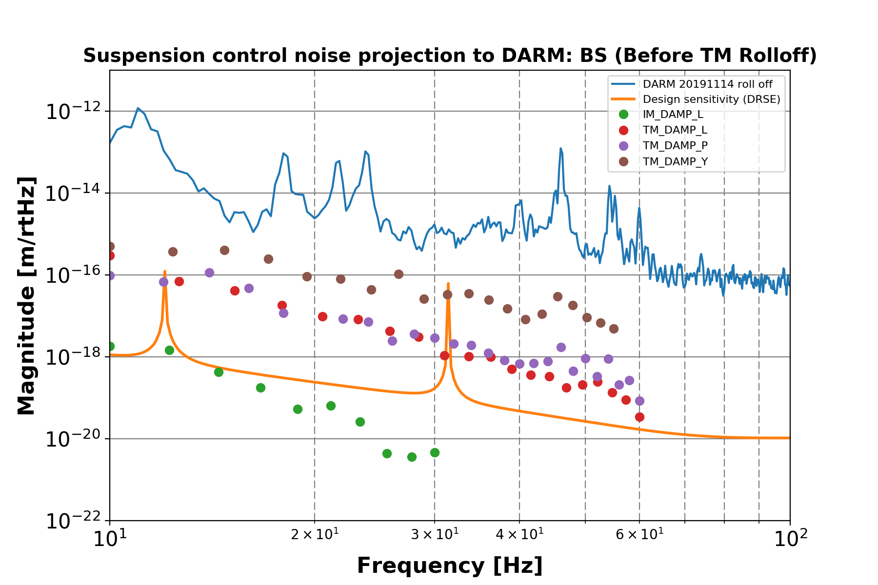
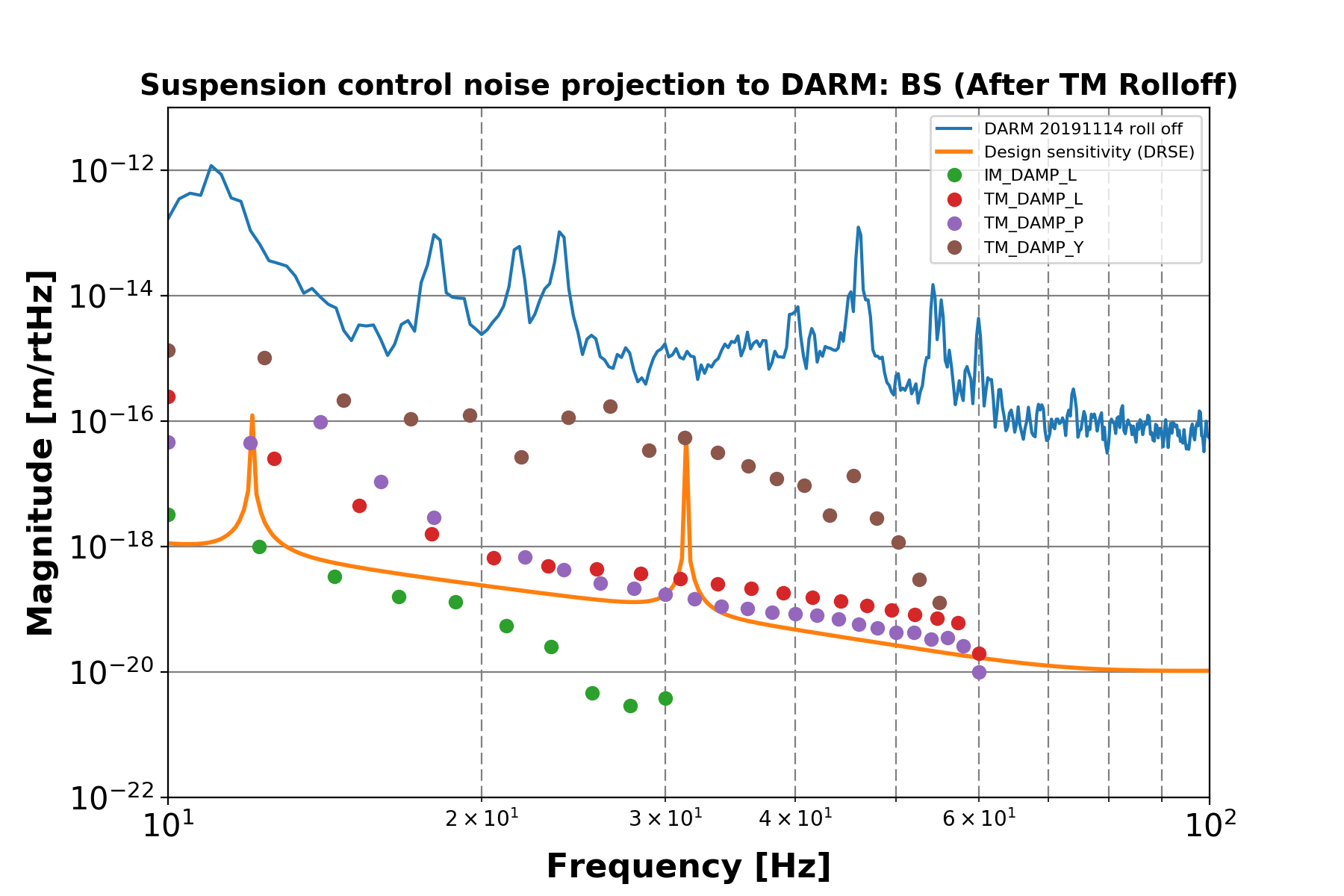
Plan for next week
- Compile and install SR real-time models.
- People have begun to modify or turn off filters which are supposed to be off in OBSEVATION state, maybe I should aim to design the bandpass filters and then implement the Guardian OBSERVATION state.
Vacation/Travel Info
~-Friday next week late in the afternoon we have the KAGRA ceremony.
Report for the week 23-09-2019
Terrence modified the real-time model in order to accomodate hierarchical actuation from the interferometer sensing and control system (ISC). The modified model has not been installed. See klog entry 10692.
In previous meetings it was reported there was a problem with the medm screen or real-time model in the components related to IP LVDT correction with the seismometer signal. In reality a trivial operation was still required. The apparent problem has been fixed now and we can proceed to implement the sensor correction in SR2 when we have the time.
Plan for next week
If we have the time it would be good to implement the sensor correction at least in the BS and test it in bad weather conditions.
Commit the changes that Terrence made to the real-time model.
Vacation/Travel Info
Friday next week late in the afternoon we have the KAGRA ceremony.
Type B
Report for the week 13-09-2019
In previous weeks we identified injected noise into the SR3 IM from the oplev (klog 10262). On Monday I put notches at various frequencies where there were peaks (klog 10423). This procedure seems to work but it's tedious and we should do it in an as-needed depending on the impact of each peak in the interferometer signal.
Shoda-san and Terrence began been working in IM-L to IM-P and IM-Y filters (klog 10505).
In a previuos week I modified the SR2 real-time model in order to do LVDT correction with the seismometer signals. This week was mainly troubleshooting and preparation: * We found a couple of errors in the real-time model (klog 10460, 10509).
Miyo-kun added ati-aliasing filter at the output of the PEM real-time model before the Dolphin network.
An integrator is needed for the seismometer signal in order to get a displacement. However, the automatically generated medm screen points to a different filter bank (klog 10510). This hasn't been fixed yet.
Still, I measured transfer functions from seismometer on the ground to IP LVDT in FLOAT state, data which can be corrected (klog 10510).
In SR2 the cables connecting the BIO output from the coil drivers to the DIO card inside the I/O chassis were connected in a wrong way. I fixed them (klog 10464 and 10508).
Type B
Report for the week 02-09-2019
Shoda-san implemented new low frequency filters for the IMs using the oplev signals (e.g. klog 10355).
With PEM team on Monday 2nd of September we put accelerometers on the two SR3 oplev platforms and on the large frame (klog 10262):
Above 10 Hz the coherence of the oplev readings with the upper platform accelerometer is high in several regions.
It was possible to identify injected oplev noise into the suspension by looking at the coherence between one of the accelerometers and the IM, including large peaks between 16 and 18 Hz.
There's more information in the diaggui file which hasn't been analyzed.
On Tuesday we moved SR2 and SRM oplev tilt QPDs to sensible positions after the commissioning team re-aligned the interferometer (klog 10291).
I checked the OSEMs position and V2 is in an uncomfortable position: only 140 um from the end of linear range.
Although until now I checked the position using the calibration information the OSEM flag has been in a nearby position for since the end of May (klog 9028).
Due to a problem with the BF keystone, the clerance in the other direction is 140 um.
We decided to keep the keystone in the current position because it hasn't created any problems so far.
Nakano-kun reported the BS was moving too much in yaw. I did some measurement and noticed the inertial damping was injecting noise below 100 mHz (klog 10354). At 50 mHz there's even a feature 2.4 times larger with inertial damping. We should just turn the inertial damping off. It also happens that according to klog 9991, it is not working so effectively in reducing the integrated RMS.
Last week I modified the real-time model to enable IP LVDT correction and feedforward with seismometer signals on the ground. On Thursday I worked inthe MEDM screen modification.
Terrence updated Guardian after a report from Shoda-san concerning SR2: Guardian was not tripping when the GAS filter coil driver hardware watchdog tripped (klog 10352). However, after the modification we realized of an additionl problem: in a situation in which the TM coil driver should trip, the GAS filter coil driver trips instead.
Plan for next week
Finish the MEDM screen modification, install the real-time model and begin setting the LVDT correction with the seismometer signal.
In order to minimize the injection of ground motion with the oplev, roll-off the oplev signal before it's used by any filter. * Use a cutoff frequency of about 8 or 9 Hz.
In order to assess the amount of oplev control noise, ask Yokozawa-san to leave the accelerometer at the oplev upper platform in order to measure its coherece of the IM degrees of freedom.
Roll-off the GAS DC control filters in order to reduce the control noise in the observation frequency band.
Do we need to extend the GAS DC control filters to the micro-seismic region?
Report for the week 26-08-2019 (Written by Fabian)
Shoda-san improved the SR3 optic pitch filter (klog 10152, 10217).
For the SR3 optic Enomoto-kun implemented an integrator filter with UGF above the micro-seismic (klog 10014). This filter used the oplve signal.
It works well, but it requires a set-point, which is currently set at the IM level (for IM DC control) not at the optic level.
A clear and clean implementation requires moving the set-point to the optic level and then take the error signal to the IM.
Nakano-kun modified the SR2 optic set-point to a place which is not so suitable for the oplev. We will move the QPD on Monday.
I modified the SR2 tower real-time model to allow for LVDT correction and feedforward with seismometer. * I had to modify the PEM real-time model to connect the seismometer channels to the Dolphin network.
Both models compile and I'm currently modifying the medm screen.
Performance report * There was a typhoon before the F2F meeting and this week we have had bad weather, in both cases there was an increase of the micro-sesmic activity.
During the typoon we saw a large peak at 150 mHz and this week we saw a peak a large peak at 60 mHz.
With bad weather Type B suspensions' optic motion (upper limit) were above the requirement in TM-L displacement and velocity: BS 10046, SR2 10052, SR3 10056, SRM 10067.
Nevertheless, in days with good weather the suspensions behave mostly well in ALGNED and FLOAT states: BS 9697, SR2 9703, SR3 9702, SRM 9704.
I also found the vertical ground motion induces motion in TM-Y and TM-P, but even with bad weather the motion remain below the requirement.
With this bad weather I was able to measure transfer functions from the ground to (klog 10170).
Plan for the week 02-09-2019
On Monday I will work with Yokozawa-san putting accelerometers on the SR3 oplev platforms. We will likely turn the fans off to do measurements.
We will move the SR2 tilt oplev QPD.
Real-time model: move the optic set-point to the optic level.
Update medm screens.
Shoda-san reported a coil-driver not working properly with the binary input/output. I need to check.
Test Shoda-san's fisnhing rod off-loading script with SRM sometime next week.
Terrence will be back on Wednesday.
Type B
Report for the week 15-08-2019 (Written by Fabian)
Shoda-san improved the SR3 optic yaw motion (klog 9949).
Improvement in the frequency band from 1 Hz to 2.3 Hz was achieved by modifying the IM-Y filter. The problem was not enough phase margin.
There's still a peak at 1.3 Hz.
She also modified the IM SENSALIGN matrix (diagonalization according to resonance peaks?)
Transfer functions should be measured again.
The BS optic has a large peak at 150 mHz (klog 9991).
Plan for the week 19-08-2019
Enomoto-kun requested to extend the oplev control loop down to where the micro-seismic peak is. (Fabian.)
Assemsment of the motion of the SR optics around the micro-seimic region. (Due today.)
Type B
Report for the week 05-08-2019 (Written by Fabian)
After Shoda-san's report (entry 9797) I checked the condition of the filters in FLOAT state.
I checked the configuration of the hardware whitening filters by checking the 32 bit dip switch boards for each supension. See entry 9823 and 9876.
The switch configuration is the same for SRM and SR2.
For BS and SR3 the configurations are different.
Additionally, the configuration of the two boards used for the BS oplev are different from each other.
This situation should be reviewed.
Type Bp and Type A don't seem to be using software anti-whitening filters for oplevs. I haven't checked their hardwate whitening filters' configuration though.
At the begining of the week I continued noise hunting in SR3. See entry 9807. The goal was to identify the limiting elements for the control system in ALIGNED state. See entries
The motion of the IP-L induces motion in TM-P and TM-L in the frequency band from 0.135 Hz to 0.4 Hz. This should be fixed at the IP. There's no inertial damping yet.
The motion of the IM-L induces motion in TM-P nd TM-L in the frequency band from 0.3 Hz to 0.8 Hz. Likely, this should be fixed with IML2TMP and IML2TML control filters.
The motion of the IM-P induces motion in TM-P and TM-L in the frequency band from 0.135 Hz to 1 Hz. The motion in the band from 0.135 to 0.4 Hz is likely ground motion coming from the IP, however, the motion from 0.4 Hz to 1 Hz should be fixed with IMP2TML and IMP2TMP control filters.
The motion in IM-Y induces motion TM-Y between 1 Hz and 2.3 Hz. This should be fixed with IMY2TMY control filters.
I began measuring transfer functions (IM-L to TM-L) but I should finish the setting the software anti-whitening filter first.
Plan for the week 15-08-2019
Finish measuring transfer functions.
Begin the design of filters.
Report for the week 7/29 (Written by Fabian)
I offloaded fishing rods in GAS filters and IPs in BS and SRM.
I implemented scripts for the automatic measurement of amplitude spectral densities (ASDs) of suspension sensors (usually used for residual motion estimation).
Highlights of recent ASD measurements can be found in entry 9726. The residual motion was measured in ALIGNED and FLOAT states.
In SRM and SR3 the motion in ALINED state was smaller than in FLOAT state, which is expected. See entries and respectively .
In SR2, the motion in pitch and yaw displacement is larger in ALIGNED state, and the longitudinal velocity is the same in both states.
In BS, the longitudinal displacement is the same in both states.
Some features of the measured ASDs are the following: * In SRM, SR3 and SR2 in pitch there is either a large bump (SRM and SR3) or excitation (SR2) between 0.3 Hz and 1 Hz. 9756.
In SRM pitch the control system seems to be introducing noise in two frequency bands, before and after the bump. See 9756.
In SR3 pitch the control loops seems to be introducing noise between 1 Hz and 2 Hz. See 9755.
In SR2 pitch the control loops seems to be introducing noise between 0.380 Hz and 2 Hz. See 9752.
In SR2 yaw the control loops seems to be introducing noise between 0.045 Hz and 0.230 Hz. See 9752.
In SR2 longitudinal speed the control system seems to excite a large peak at 0.705 Hz. See 9752.
Plan for the week 8/5
Check the BS amplitude spectral densities.
Check the longitudinal degree of freedom in SRs.
Aim to identify noise sources.
Type B
Report for the week 7/22 (Written by Fabian)
Shoda-san set the auto-measurement scripts and directories. She measured the transfer functions having the suspensions in FLOAT state.
SR3 IM H2 OSEM channel noise hunting (klog 9613 and 9629).The symptom was that the noise in SR3 IM H2 channel was 4.7 times larger than in similar channels. When the suspension was quiet H2 was not measuring any displacement but only noise. We did several measurements:
We removed the cable from the satellite box at the AA filter input and terminated the input: the noise was still there.
We terminated the ADC from the inside of the AA filter box: the noise was gone, suggesting the problem was the AA filter.
We replaced the AA filter and repeated the measurement with the input terminated: the noise was still there.
We disconnected all the cables from the input of the AA filter and terminated the offending channel: the noise was still there.
We also changed cables and tried connecting the AA filter to the SRM rack but the noise was still there.
The solution was to use other channels for all IM-H OSEMs. The real-time model was changed accordingly.
The SR3 LVDT driver broke down (klog 9659).
We changed the AA filter power cable and when we turned the filter back on the whole rack turned off momentarily and came back on, with the exception of the LVDT driver.
We tried turning it on but it kept switching off by itself. Tomura-san suspects there's a grounding problem.
We decided to change the driver.
LDVT driver replacement and adjustment (klog 9658 and 9025).
For each channel there are three resisitors which require adjustment and determine an input gain, an output gain and a phase.
The phase was originally measured with an oscilloscope and the resistor was adjusted using also the oscilloscope.
The output gain resistor was set to the desired value using the multi-meter.
For the input gain we tried mesuring the signal amplitude with the oscilloscope (per Nikhef instructions) but we didn't see any obvios change when changing the resistence value.
Alternatively we measured the input resistence values in the old cards and set the new ones accordingly.
We did quick measurements of transfer functions and they looked alright. Measurements with better frequency resolution are needed.
Plan for the week 7/29
Noise assessment in SR3. * IM-Y integrated RMS displacement with control system on. Compare with klog 9494.
Terrence verbally reported LVDTs are particulrly noisy.
I would like to measure ASD for all sensors (in FLOAT state) and compare with other suspensions.
Miyakawa-san is interested to find the origin of the noise in one particular channel.
Check SRM BF position. The set point should be zero (klog 8672) but today I realized it was set to 100 um sometime.
Check if we need to offload coil-magnet actuation onto fishing rods.
Remove the software de-white (OSEMs) and antiWTN (oplevs) filters used in some or all suspensions. We don't have hardware whitening filters at the input.
Compile information about Guardian states and make it available to all.
Vacation/Travel Info
Terrence left Kamioka. He will be back on September.
Type B (Mark)
Report for the week 7/15 (Written by Fabian)
SR3 IM H2 noise hunting.
SRM oplev condition: when the suspension is in ALIGNED state the oplev (pitch) is saturated and yaw within an inconvenient range (non-linear). See klog entry 9562.
Currently we don't have a good reference for the optic alignment and we cannot decide by how much we should move the QPD. This situation is not new and we tried to cope with it by using historical data of IM DC feedback signal in a good orientation for the DRMI. However, this strategy didn't work.
The consequence is that in ALIGNED state the pitch feedback DC signal drifts.
Kokeyama-san and Valera aligned the mirror, provided a reference and we were able to move the QPD. See entry 9579.
The big flange was moved to another place.
BS IM2TM transfer functions were measured in ALIGNED state with the control system on. See entry 9571.
HPCD modification. See entry 9541 and comments.
Plan for the week 7/22
Go back to the tunnel on Monday to continue the investigation in SR3 IM H2 OSEM noise.
Vacation/Travel Info
Terrence goes back to Hong Kong on 7/27 (sat), last day in Kamioka: 7/25 (Thurs).
Type B (Mark)
Report for the week 7/8 (Written by Fabian)
There was DAQ channel update on Wednesday.
After making a wind shield for SR3 oplev last week Terrence revisited the design of the IM to TM control filter with oplev and tried to reduce the residual motion peak at 1.4 Hz reported by Izumi-san.
Last week we moved all the SRs oplev QPDs because they were off by an unsuitable amount. After the interfrometer was aligned again we realized some QPDs will likely require to be adjusted again (optimal position would be within ±50 in normalized displacement units): SR2 tilt and SRM tilt require further adjustment.
During DRMI commissioning people realized the SR3 yaw motion was too large and was compromising the stability. * The yaw peak-to-peak motion was 6 µrad and involved IM/RM/TM resonat modes at ~0.147 Hz and ~0.172 Hz.
Terrence realized the amplitude decreased just by turning off the IM yaw control. He tried to damp IM-Y with the oplev but more time is required.
We realized the H2 IM OSEM is likely too noisy and excites resonant motion. We went to the mine, checked the LED current monitor but couldn't find anything obviously wrong using the oscilloscope. More investigation is needed.
Enomoto-kun pointed out that the IM2TM oplev DC control might be marginally stable. Terrence measure the IM-Y to TM-Y transfer function and designed the filter again allowing a suitable phase margin at 0.14 Hz.
In the satellite boxes the label "CURR Mon. for PD" should be "CURR Mon. for LED".
SR3 and SRM oplev sled are decreasing their power (e.g. 50% in 150 days in SR3). The situation has been reported to Akutsu-san already.
Fabian came up with a preliminary plan to search for common mode motion in Type B systems (after talking with Miyo-kun, Terrence and Lucia.)
Report the status of the control system.
Plan for the week 15/8
Go back to the tunnel on Tuesday to continue the investigation in SR3 IM H2 OSEM noise.
Measure and provide IM-L to TM-P transfer functions to the commissioning team (Stefan's request this morning).
Vacation/Travel Info
Terrence goes back to Hong Kong on 7/27 (sat), last day in Kamioka: 7/25 (Thurs).
Type B (Mark)
Report for the week 7/1 (Written by Fabian)
Fabian and Terrence went through the process of oplev diagonalization for the purposes of knowledge transfer and procedure documentation. * There were small corrections to the procedure.
Terrence wrote the oplev section of the Type B paper.
Fabian began writing a rough draft of the procedure.
With the agreement of the comissioning team we decided to move the position of all of oplev QPDs. When the optics were aligned they were away from linear range. * Although the badly affected channels were only three, we decided to adjust all of them.
The procedure is described in klog entry 9411.
In order to keep the aligmment information, we took note of the IM DC control signal necessary to achive the alignment and and off-loaded the actuation onto the TEST channels while the oplev was adjusted with the control system off.
In the case of SRM the oplev was to the point of saturation and was not rendering a usable feedabck signal when the optic was alledgely in aligned state. In this case we looked for the appropriate amount of feedback in stored data from a time in which the DRMI had been locked.
On Friday we went to the tunnel in order to put a better wind shield around SR3 oplev optics. The aim is to reduce the noise and then improve the performance of the control system.
We found large and heavy blank flanges leaning on the large SR3 and SRM frames. Removing them will likely disturb the position of the IPs, which would require readjustig the QPDs again. We would like the flanges to remain there for O3 if possible. Fabian will write a message to the vacuum group with our request.
Plan for the week 7/8
Terrence and Fabian will continue writing the oplev diagonalization procedure.
Fabian will install the rolled-off the DC control filters.
Type B (Mark)
Report for the week 6/24 (Written by Terrence and Fabian)
Type B watchdog/DACKILL is split for tower and payload. Now, tripping the payload watchdog will only trigger the payload DACKILL while tripping the tower watchdog will trigger both watchdogs and DACKILL. The MEDM screen is updated to accommodate the changes. The screen is also modified so the reset buttons for watchdogs and DACKILL are all available on the same screen. In the middle of this work, a bug is discovered in the ModerateWD.c where setting 0 to the ramp down time would cause the WD to loop in an endless ramp down cycle.
The Guardian is updated to recognize if the payload is tripped and decide which tripped state it should go to, "TRIPPED" or "PAYLOAD_TRIPPED". So, if both tower and payload controls are on while the payload watchdog tripped, the guardian will jump to the "PAYLOAD_TRIPPED" state and shutdown payload controls only. When the WD and DACKILL are reset, the "TRIPPED" state will dump you out to the safe state where all controls are disengaged, while the "PAYLOAD_TRIPPED" state will dump you out to the "ENGAGING_IM_DAMPING" state where the tower controls are still on.
VIS monitor is updated. It will monitor the raw sensor input and actuator output and check if they are within the operation range. The indicator will turn orange when it is 50% out of range and will turn red if it is 90% out of range. The indicator for actuators will turn blue if they are not in use. The limits of the operating range can be set in userapps/vis/k1/guardian/VIS_DICT.py. The range for OL_PIT and OL_YAW are default to be [-1,1], the lower limit of the OL_SUMs are default to be 1000 counts while those for the other are default to be [-32768,32768].
If you know the range of certain sensors and actuators, you are strongly encouraged to tweak the thresholds in the file. Otherwise, the function of the monitor will be very limited.
Fabian checked again the GAS filter control noise: * My previous calculation considered damping filters and those injected too much noise in the observation frequency band. Rolling the filters off with (high order) Butterworth filters rendered the system unstable.
I then considered DC control filters only and I was able reduce the injectetd noise to acceptable levels while keeping the loop stable. As pointed out by Shoda-san, this was the strategy devised for the Type B prototype.
This has only been tested in software, not in the actual system. I aim to do implement it next week.
This strategy will work only if the resonant motion of the system is not excited after disabling the payload and GAS chain damping control. On the 23rd of May Terrence measured the residual motion with the control system (including IP) on and off. There was no subtantial difference between the two. I aim to take more measurements.
Terrence and Fabian are currently going through the oplev diagonalization procedure and will write down the procedure.
Hirata-san worked in the design of the baffles for the BS.
Plan for the week 7/1
Terrence and Fabian will continue writing the oplev diagonalization procedure.
Fabian will install the rolled-off the DC control filters.
Vacation/Travel Info
Terrence goes back to Hong Kong on 7/27 (sat), last day in Kamioka: 7/25 (Thurs).
Mark's final day 6/28.
Type B (Mark)
Report for the week 6/17
Izum-san pointed out the SR3 oplev control loop was not able to damp resonances at 1.4 Hz and 1.2 Hz (klog 9290). Terrence checked (klog 9299):
He found that the optic TFs were coupled to about 10%. I assume something changed because, as far as I understand (Fabian), the oplev had been succesfully diagonalized before to less than 1% coupling.
He moved the IP and compared IP LENGTH with OPLEV LENGTH noting the the oplev was reading only 70% of the IP displacement.
In this conditions he diagonalized the oplev but failed. There was still coupling.
He introduced a factor to have the OPLEV LENGTH measurement equal to IP LENGTH measurement.
He successfully diagoinalized the oplev.
He then proceeded to checked the filter but he was unable to reduce the residual motion. Noise is the suspect. Having appropriate wind shield is recommended.
Fabian worked in rolling-off the control filters of the GAS filters. * According to klog 8979 the GAS filter control noise has to decrease by 5 orders of magnitude in order to meet the requirement at 10 Hz.
A Butterworth filter of order 20 with a cut-off frequency of 5 Hz seems to reduce the noise but renders the system unstable.
More work is necessary.
Fabian joined Enomoto-kun's lecture on how to align the X Fabry Perot cavity with green light.
Plan for the week 6/24
Terrence will work on...
Fabian will continue working in the rolling-off of the filters of the GAS filters control loops.
Vacation/Travel Info
Terrence goes back to Hong Kong on 7/27.
Mark's final day 6/28.
Type B (Mark)
Report for the week 6/10
Supporting the commisioning team.
BS
Type B inertial damping. This means geophone diagonalization, blending filter optimizing, etc.
Optimization gives an odd looking blending filter that blends at ~120 Hz, but works fine in IP L. 9199
During PRMI lock, BS residual motion was too high which misaligned the beam too much from time to time and making the lock unstable.
To fix this, I improved OL windshield so I can study the residual motion of the BS. Then I copied IP L blending filter to IP T and IP Y and cranked up the IP damping and TM damping gain. This suppressed the residual motion so the requirements are met. After this, the BS was not causing any problem to the lock anymore. 92199235
Type B (Mark)
Report for the week 6/3
SRM Inertial Damping and Residual Motion Stuff
See Klog 9064
SRM IP L and T is blended at ~110 mHz (partially optimized by gradient descent, stopped after 10 iterations, then manually adjusted.) while IP Y is blended at 260 mHz (Lucia's old filter). The stability test was carried over the past weekend with inertial damping and all other stages on. The system seems stable.
To study to performance of the inertial damping, I improvised an OL windshield for SRM.
Another round of diagonalization was carried just because we have better sensitivity.
With IP LVDT damping and other controls on, the residual motion is as follows 9086:
RMS Displacement: Requirement Result L 0.4 µm 0.1076 µm P 1 µrad 0.0569 µrad Y 1 µrad 0.0598 µrad
RMS Velocity: Requirement Result L 0.5 µm 0.1014 µm/s P / 0.2165 µrad/s Y / 0.1776 µrad/s
I measured the residual motion with inertial damping, inertial damping without LVDT DC, normal damping without LVDT DC. Results are pretty similar.
I modified the optimization algorithm to allow fine learning. The cost plateaued after ~300 iterations and the blending frequency was at 78.6 mHz. I tried implementing this blending filter but the system went unstable.
SR3 Inertial Damping
The calibration, diagonalization for IP geophones was done.
I measured and fit noise floor for LVDTs and geophones.
I found that the IP geophones have a much higher noise level than those from SRM. (1 order of magnitude higher, see 9088)
This explains why the optimization result of the blending filter converges much quicker than that of SRM, because the geophone noise level limits the blending frequency to be at ~ 130 mHz.
However, when the system went unstable when the blending filter was implemented. I should try a higher blending frequency or manually adjusting the blending filter to have a proper shape.
Type B (Mark)
Report for the week 5/27 (written by Fabian)
Shoda-san implemented the moderate watchdog: when tripping the amount of actuation will ramp down to zero smoothly. Klog entry 9009.
Terrence updated the BS guardian.
Terrence designed a VIS status monitor. The font might be too small for some people.
Terrence worked on SRM inertial damping. * There is coherence between the geophones and LVDTs at 0.1 Hz.
He designed a filter with a blending frequency of 0.110 Hz.
The system seems stable.
For SR2 Fabian calculated the sensor noise fed back into the system by the control loop: entry 8979.
The GAS filters' contrbution is too high.
I asked Enzo and he didn't rolled off the filters at higher frequecies.
Filter modification was assigned to Fabian.
Fabian and Yokozawa-san measured the settings of the SR3 LVDT driver. Klog entry 9025.
In the weekly comissioning meeting Fabian made the commitment of writing a list of the measurements we want to do with the DRMI for Type B characterization.I will write it by next week and send it around for comnents.
Type B (Mark)
Report for the week 5/20 (written by Fabian)
Terrence implemented a filter for the inertial damping. See entry 8905.
The highlight of the week is Terrence's measurement of the residual motion of the SR2 optic: as measured by the oplev, it does fulfill the RMS displacement and velocity requirements for lock acquisition and, partially, for the observation mode also. See the report at klog entry 8949.
The integrated RMS was calculated from 5 Hz to DC because there are some peaks between 8 Hz and 10 Hz and whose origin still has to be clarified. See the report at entries 8918 and 8933.
After Akutsu-san's suggestion Terrence improved the air shield in two rounds, including a cylindrical cover around the viewport. This reduced the noise by about a factor of 10.
He realized setting up the shield may have slightly changed something in the oplev and carried out another round of diagonalization.
He realized the H3 coil was not working. We fixed it.A cable was disconnected.
The optic residual motion in L showed a large peaks close to 0.2 Hz, which is where the micro-seismic may become apparent. The peak was not seen in P or Y. The inertial damping system is likely not working in a suitable way. The blending frequency is 0.190 Hz which may not be low enough.
At the end measurement of the residual motion reported was carried out with inertial damping only in yaw.
Fabian, Terrence and Fujii-kun measured the settings of the SR2, BS LVDT drivers and one of SR2's. See klogs 8941 , 8951 and 8952.
Fabian worked more on the calculation of the amount of sensor noise injected: * I imported Panwei's OSEM noise measurements and calculated the virtual sensor noise.
I imported Fujii-kun's measuement of the geophone noise and calculated the virtual sensor noise.
I imported the blending filter
I wrote lots of comments in Sekiguchi-kun's Matlab scripts.
I will write a klog soon with preliminar results.
Fabian submitted and abstract for the Autumn JPS meeting on September.
Plan for the week 5/25
Terrence will work in the optimization of the inertial damping.
Fabian will continue with the calculation and prepare a presentation for the conference in Brazil.
Report for Golden Week
Mark monitored vent and pumpdown, and worked on vistools.py.
Report for the week of 5/6
Lucia and Terrence got the blending working for the IP LVDTs and geophones.
Terrence and Mark modified the models and MEDM screens to add a new IP block, IDAMP, for damping using the blended signal with inertial information, and a new DAMPMODE block for ramping smoothly between IDAMP and the old DAMP.
Mark worked on vistools.py, improving the support for cdsMuxMatrix blocks (e.g., OSEM2EUL) and adding support for cdsRampMuxMatrix blocks (e.g., the newly introduced DAMPMODE). He also created two sets of unit tests, unittest.py and unittest.sh, for the two modes of use (as a Python module in other Python programs, and as a command-line utility in bash).
Report for week of 5/13
Terrence measured Q's for nearly all modes on SR2 from TFs and then did some ring-down tests to get a better estimate of some high-Q modes.
Terrence and Mark looked at the velocity and angular velocity noise of the SR2 as reported by the LEN and TILT OLs. * The Y signal was fairly clean and the Y RMS angular velocity requirement was met. However the L signal was quite noisy, and was also contaminating the P signal due to the large cross terms in the diagonalization matrix. The RMS L from 5 Hz down with damping on was around 10 µm/s, which is 10 times the requirement. However little of this was due to pendulum resonances - most of the noise was featureless and broadband. In displacement units the noise was flat up to about 1 Hz and then smoothly rolled off to f^-2. The noise in the raw P and Y signals (not yet divided by the sum) was about 10 times the noise in the SUM.
We tried improving the noise with different whitening settings. Increasing the overall gain, increasing it at the QPD but reducing it at the whitening filter, and switching off the 1-10Hz boost whitening filter (and compensating software filter) had no effect. Blocking the beam reduced the noise by about 2 orders and brought the raw P and Y in line with the SUM, suggesting that the problem was before the QPD. Akutsu-san says the noise spectrum looks like it may be limited by air currents, and we probably need better wind shielding.
Mark swapped in an improved version of vistools.py, debugged a few small issues, and simplified the TYPEB.py Guardian.
Fabian embarked on a project to calculate the residual motion within KAGRA's observation band (beginning at 10 Hz) to make sure The Type B suspension fulfills the requirement, and calculate the speed of the optic to make sure we can acquire the lock. * He modified Takanori's Simulink/Matlab simulation in order to include the length sensing oplev and its control feedback path.
He imported Enzo's IM/GAS/IP-LVDT filters into the simulation.
He imported into the simulation the measured LVDT floor noise (sensitivities).
He calculated the IP-L, IP-T and IP-Y sensitivities.
Plan for week of 5/20
Mark at Mitaka Mon, Tue; US from Wed till 6/11.
Fabian * Import Panwei's OSEM sensitivity measurements and calculate the sensitivity of the virtual IM sensors.
Import geophones sensitivities and calculate the sensitivity of the corresponding virtual sensors.
Import Licia's and Terrence's inertial sensing filters.
Terrence * Try to reduce the OL noise and get better estimates of the RMS velocity with damping on.
Vacation/Travel Info
Terrence's next visit from 4/18 to 7/27.
Mark's final day 6/28.