|
⇤ ← Revision 1 as of 2010-12-08 16:30:28
Size: 274
Comment:
|
Size: 562
Comment:
|
| Deletions are marked like this. | Additions are marked like this. |
| Line 8: | Line 8: |
| {{attachment:ResonantCurves.png}} | {{attachment:ResonantCurves.png|width=800}} Only the upper sidebands are plotted here. It is clear that the two sidebands get different phase shifts when reflected by the arm cavities. It is desirable to have them both at exactly an anti-resonance. However, it is not possible unless we change the arm length a lot. |
Arm Cavity Design
RF Sideband resonance in the arm cavities
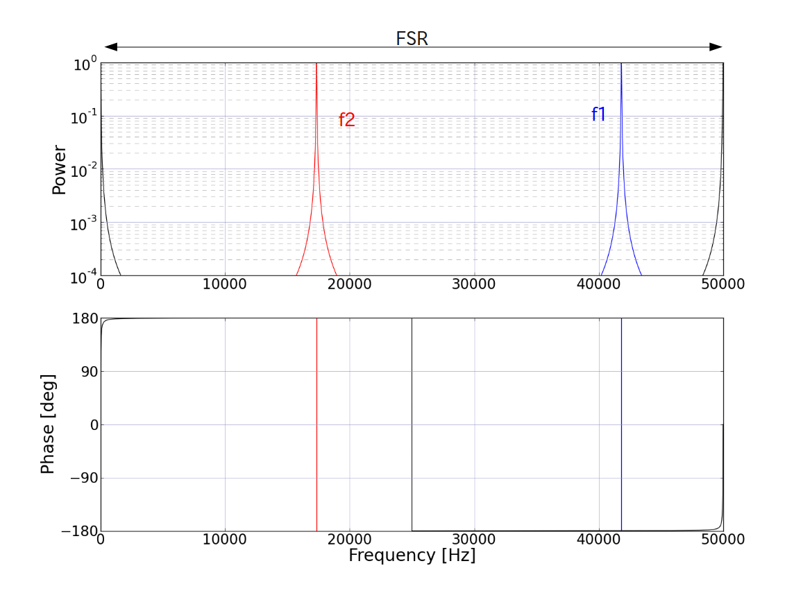
We have to avoid RF sidebands to be resonant in the arm cavities. For example, canonical parameters (L=3000.0, f1=11.25MHz) give the following resonant curves.

Only the upper sidebands are plotted here. It is clear that the two sidebands get different phase shifts when reflected by the arm cavities. It is desirable to have them both at exactly an anti-resonance. However, it is not possible unless we change the arm length a lot.
