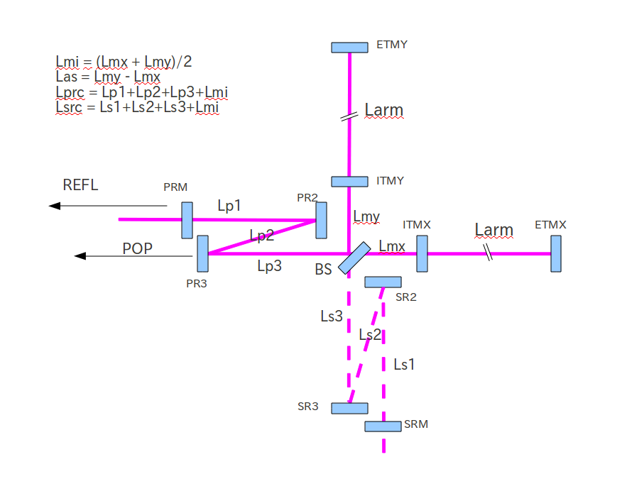
|
⇤ ← Revision 1 as of 2011-07-04 13:25:46
Size: 328
Comment:
|
Size: 598
Comment:
|
| Deletions are marked like this. | Additions are marked like this. |
| Line 7: | Line 7: |
| {{attachment:LCGT/subgroup/ifo/MIF/OptParam/MIF-diagram.png|MIF Diagram|width=800}} |
|
| Line 8: | Line 10: |
| || ||Lp1 ||Lp2 ||Lp3 ||PRM ROC||PRM Beam Size||PR2 ROC||PR2 Beam Size||PR3 ROC||PR3 Beam Size|| ||Case 1||14.76m||12.07m||14.76m||310.42m||4.05mm||-3.13m||4.05mm||27.01m||35.43mm|| |
Layout related issues
Location of PR2 tank
Is it possible to put the PR2 and SR2 vacuum chambers further away from the BS chamber ? The minimum separation is 2.7m (center-to-center). However, in order to improve the workability around the BS chamber, we want increase the separation.

Comparison Table
|
Lp1 |
Lp2 |
Lp3 |
PRM ROC |
PRM Beam Size |
PR2 ROC |
PR2 Beam Size |
PR3 ROC |
PR3 Beam Size |
Case 1 |
14.76m |
12.07m |
14.76m |
310.42m |
4.05mm |
-3.13m |
4.05mm |
27.01m |
35.43mm |
