|
Size: 328
Comment:
|
Size: 1692
Comment:
|
| Deletions are marked like this. | Additions are marked like this. |
| Line 2: | Line 2: |
| <<TableOfContents(3)>> | |
| Line 7: | Line 7: |
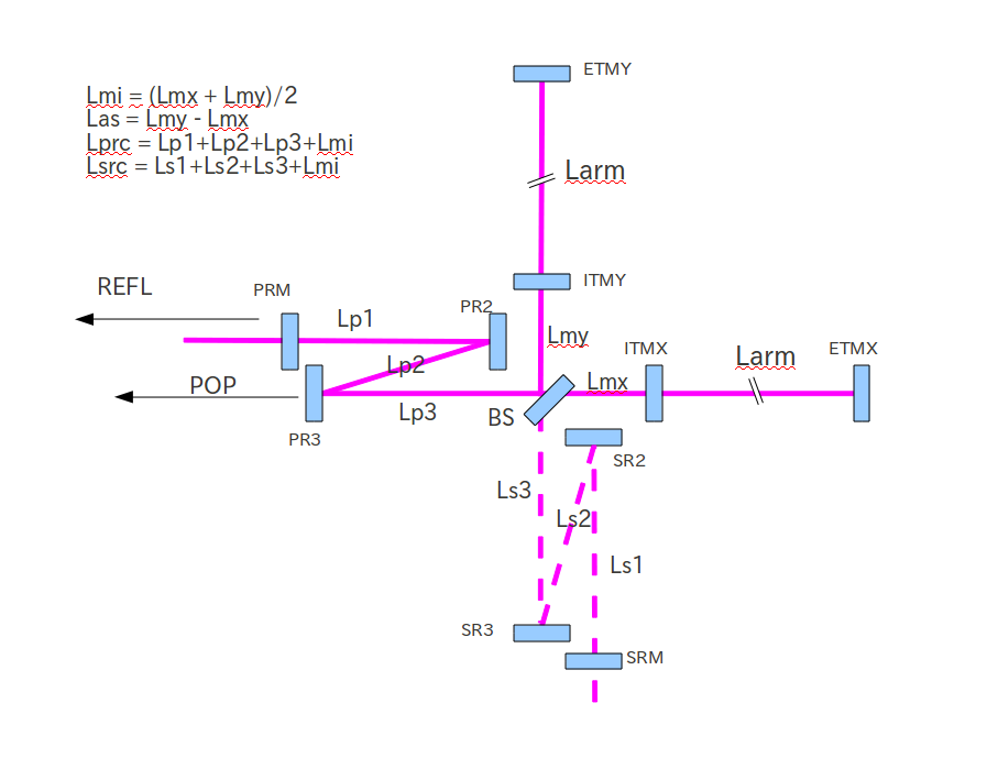
| {{attachment:LCGT/subgroup/ifo/MIF/OptParam/MIF-diagram.png|MIF Diagram|width=800}} |
|
| Line 8: | Line 10: |
L_BS_PR2 is the separation between the center of BS chamber and the center of PR2 chamber. The following table shows the the Folding parameters with three different cases of L_BS_PR2. Case 1 is the default plan. Case 2 adds 2m to the BS-PR2 separation, and Case 3 adds 3m. Note that the arm cavity g-factor is assumed to be negative (1.5km-1.9km), which usually gives slightly smaller beam sizes on the PRM. || ||L_BS_PR2||Folding Angle||Lp1 ||Lp2 ||Lp3 ||PRM ROC||PRM Beam Size||PR2 ROC||PR2 Beam Size||PR3 ROC||PR3 Beam Size|| ||Case 1||2.7m||0.63deg||14.76m||12.07m||14.76m||310.42m||4.05mm||-3.13m||4.05mm||27.01m||35.43mm|| ||Case 2||4.7m||0.67deg||14.09m||11.40m||16.10m||295.3m||3.95mm||-2.88m||3.95mm||25.45m||35.46mm|| ||Case 3||5.7m||0.69deg||13.76m||11.06m||16.76m||287.75m||3.91mm||-2.75m||3.91mm||24.67m||35.48mm|| === Layout files === The optical layout files corresponding to the above cases. [[https://granite.phys.s.u-tokyo.ac.jp/svn/LCGT/trunk/mif/OptLayout/Layout/bLCGT_OptLayout.dxf|Case 1]] [[https://granite.phys.s.u-tokyo.ac.jp/svn/LCGT/trunk/mif/OptLayout/Layout/bLCGT_OptLayout_add2m.dxf|Case 2]] [[https://granite.phys.s.u-tokyo.ac.jp/svn/LCGT/trunk/mif/OptLayout/Layout/bLCGT_OptLayout_add3m.dxf|Case 3]] |
Layout related issues
Location of PR2 tank
Is it possible to put the PR2 and SR2 vacuum chambers further away from the BS chamber ? The minimum separation is 2.7m (center-to-center). However, in order to improve the workability around the BS chamber, we want increase the separation.

Comparison Table
L_BS_PR2 is the separation between the center of BS chamber and the center of PR2 chamber. The following table shows the the Folding parameters with three different cases of L_BS_PR2. Case 1 is the default plan. Case 2 adds 2m to the BS-PR2 separation, and Case 3 adds 3m.
Note that the arm cavity g-factor is assumed to be negative (1.5km-1.9km), which usually gives slightly smaller beam sizes on the PRM.
|
L_BS_PR2 |
Folding Angle |
Lp1 |
Lp2 |
Lp3 |
PRM ROC |
PRM Beam Size |
PR2 ROC |
PR2 Beam Size |
PR3 ROC |
PR3 Beam Size |
Case 1 |
2.7m |
0.63deg |
14.76m |
12.07m |
14.76m |
310.42m |
4.05mm |
-3.13m |
4.05mm |
27.01m |
35.43mm |
Case 2 |
4.7m |
0.67deg |
14.09m |
11.40m |
16.10m |
295.3m |
3.95mm |
-2.88m |
3.95mm |
25.45m |
35.46mm |
Case 3 |
5.7m |
0.69deg |
13.76m |
11.06m |
16.76m |
287.75m |
3.91mm |
-2.75m |
3.91mm |
24.67m |
35.48mm |
Layout files
The optical layout files corresponding to the above cases.
