|
Size: 3479
Comment:
|
← Revision 30 as of 2018-03-27 09:54:33 ⇥
Size: 4809
Comment:
|
| Deletions are marked like this. | Additions are marked like this. |
| Line 1: | Line 1: |
| = Mode matching optical system of Green Lock System = | = Mode matching optical system for ALS at the side of PR2 and SR2 = |
| Line 3: | Line 3: |
| <<TableOfContents(3)>> | Last modified : 2017/09/04 |
| Line 5: | Line 5: |
| ----- | Under investigation : Which is the better of the 2 lens or 3 lens <<TableOfContents(4)>> ------ |
| Line 9: | Line 13: |
| === Y-axis === | === For Y-arm === |
| Line 13: | Line 17: |
| ||SR2 (AR-surface)||1.141436 + 0.026444i||1.145506 + 0.026587i||0.066919||0.067099||2.889234||2.891750|| ||SR2 (HR-surface)||1.485931 + 0.040023i||1.488242 + 0.040171i||0.082325||0.082478||3.057627||3.056715|| ||SR3 (Input)||12.597431 + 0.040024i||12.599742 + 0.040171i||0.082325||0.082478||25.912690||25.869443|| ||BS (HR-surface)||-1017.395806 + 291.640196i||-1017.396204 + 291.640312i||7.027560||7.027562||25.503215||25.503220|| |
||SR2 (AR-surface)||1.141658 + 0.026444i||1.145729 + 0.026587i||0.066919||0.067099||2.889797||2.892313|| ||SR2 (HR-surface)||1.485931 + 0.040023i||1.488242 + 0.040171i||0.082325||0.082478||3.057628||3.056716|| ||SR3 (Input)||12.597431 + 0.040023i||12.599742 + 0.040171i||0.082325||0.082478||25.912697||25.869453|| ||BS (HR-surface)||-1020.981427 + 292.656219i||-1017.458984 + 291.640312i||7.039791||7.027562||25.548554||25.504674|| |
| Line 20: | Line 24: |
| === X-axis === | === For X-arm === |
| Line 24: | Line 28: |
| ||PR2 (AR-surface)||1.179513 + 0.026317i||1.181989 + 0.026422i||0.066757||0.066891||2.992774||2.993064|| ||PR2 (HR-surface)||1.530937 + 0.039779i||1.533251 + 0.039928i||0.082075||0.082228||3.159777||3.158650|| ||PR3 (Input)||12.597037 + 0.039779i||12.599351 + 0.039928i||0.082075||0.082228||25.991002||25.947259|| ||BS (HR-surface)||-1024.352272 + 292.664734i||-1020.788469 + 291.640312i||7.039893||7.027562||25.626193||25.581808|| |
||PR2 (AR-surface)||1.180362 + 0.026317i||1.182840 + 0.026422i||0.066757||0.066891||2.994930||2.995218|| ||PR2 (HR-surface)||1.530937 + 0.039779i||1.533251 + 0.039928i||0.082075||0.082228||3.159778||3.158651|| ||PR3 (Input)||12.597037 + 0.039779i||12.599351 + 0.039928i||0.082075||0.082228||25.991009||25.947268|| ||BS (HR-surface)||-1024.352551 + 292.664734i||-1020.788880 + 291.640312i||7.039893||7.027562||25.626199||25.581817|| |
| Line 31: | Line 35: |
| ----- | ------ |
| Line 35: | Line 39: |
| __'''Conditions'''__ | ||Conditions|| |
| Line 37: | Line 41: |
| ・ Waist radius of the beam from the fiber coupler = 350um (measured) | * The waist radius of the transmitted beam from the fiber = 350um (measured) |
| Line 39: | Line 43: |
| ・ Optical path length from AR-surface of SR2/PR2 to the optical table ~ 2m | * Optical path length from AR-surface of SR2/PR2 to the optical table ~ 2m |
| Line 41: | Line 45: |
| ・ Assume CVI lenses | * Assume CVI lenses |
| Line 43: | Line 47: |
| ---- | ----- |
| Line 51: | Line 55: |
| ||<|2>Mirror||<-2>q-parameter||<-2>Waist radius [mm]||<-2>Beam radius [mm]|| ||qx||qy||W0x||W0y||Wx||Wy|| ||Fiber coupler||<-2>0 + 0.723393i||<-2>0.350||<-2>0.350|| ||L1 (Input)||<-2>0.220 + 0.723393i||<-2>0.350||<-2>0.365828|| ||L1 (Output)||<-2>-0.108344 + 0.015935i||<-2>0.051947||<-2>0.356989|| ||L2 (Input)||<-2>0.759858 + 0.016086i||<-2>0.051947||<-2>2.199920|| ||L2 (Output)||<-2>-0.865307 + 0.026488i||<-2>0.066974||<-2>2.188928|| ||SR2 (AR)||<-2>1.143693 + 0.026488i||<-2>0.066974||<-2>2.892571|| ||SR2 (HR)||1.489013 + 0.040119i||1.485169 + 0.039991i||0.082425||0.082292||3.060270||3.057282|| ||ITMy (HR)||-1463.753784 + 729.531387i||-1538.350364 + 822.405327i||11.114831||11.801137||24.917463||25.031092|| ||ETMy (HR)||1536.246216 + 729.531387i||1461.649636 + 822.405327i||11.114831||11.801137||25.910643||24.066063|| {{attachment:BeamRadius_FC_ITMY_2lens_170903.png|Y-axis Beam radius|width="800"}} {{attachment:BeamRadius_FC_ETMY_2lens_170903.png|Y-axis Beam radius|width="800"}} ---- |
|
| Line 55: | Line 76: |
| ==== Simulation of beam parameters using above optical system with FINESSE ==== |
|
| Line 60: | Line 79: |
| ||L1 (Input)||<-2>0.095 + 0.723393i||<-2>0.350||<-2>0.353005|| ||L1 (Output)||<-2>-0.108744 + 0.016016i||<-2>0.520787||<-2>0.357411|| ||L2 (Input)||<-2>0.759744 + 0.016016i||<-2>0.520787||<-2>2.470960|| ||L2 (Output)||<-2>-0.699938 + 36.041929i||<-2>2.470500||<-2>2.470966|| ||L3 (Input)||<-2>1.324938 + 36.041929i||<-2>2.470500||<-2>2.472169|| ||L3 (Output)||<-2>-0.973537 + 0.026516i||<-2>0.670087||<-2>2.461182|| ||SR2 (AR)||<-2>1.143463 + 0.026516i||<-2>0.670087||<-2>2.890476|| ||ITMy (HR)||-1463.290098 + 730.177686i||-1537.778046 + 823.090006i||11.119753||11.806048||24.904507||25.018072|| ||ETMy (HR)||1536.709902 + 730.177686i||1462.221956 + 823.090006i||11.119753||11.806048||25.909775||24.068022|| |
||L1 (Input)||<-2>0.089 + 0.723393i||<-2>0.350||<-2>0.352639|| ||L1 (Output)||<-2>0.108858 + 0.016086i||<-2>0.052192||<-2>0.357035|| ||L2 (Input)||<-2>0.759858 + 0.016086i||<-2>0.052192||<-2>2.465986|| ||L2 (Output)||<-2>0.434746 + 35.905184i||<-2>2.465809||<-2>2.465990|| ||L3 (Input)||<-2>1.019746 + 35.905184i||<-2>2.465809||<-2>2.466803|| ||L3 (Output)||<-2>-0.973312 + 0.026619i||<-2>0.067139||<-2>2.455838|| ||SR2 (AR)||<-2>1.143688 + 0.026619i||<-2>0.067139||<-2>2.885427|| ||SR2 (HR)||1.489002 + 0.040318i||1.485159 + 0.040189i||0.082629||0.082496||3.052712||3.049731|| ||ITMy (HR)||-1461.017819 + 731.892574i||-1535.118889 + 824.885592i||11.132804||11.818919||24.856063||24.969411|| ||ETMy (HR)||1538.982181 + 731.892574i||1464.881111 + 824.885592i||11.132804||11.818919||25.921818||24.087634|| {{attachment:BeamRadius_FC_ITMY_3lens_170903.png|Y-axis Beam radius|width="800"}} {{attachment:BeamRadius_FC_ETMY_3lens_170903.png|Y-axis Beam radius|width="800"}} ----- |
| Line 72: | Line 97: |
------ == Lens displacement == === For Y-arm === ==== Pattern A (2 lenses) ==== [[attachment:GreenModeMatch_2lens_170904.pdf]] ---- ==== Pattern B (3 lenses) ==== [[attachment:GreenModeMatch_3lens_170904.pdf]] |
|
| Line 74: | Line 118: |
| == Beam radius from the fiber coupler to arm cavity == | |
| Line 76: | Line 119: |
| === Y-axis === {{attachment:BeamRadius_FC_ITMY_3lens_170830.png|Y-axis Beam radius|width="800"}} {{attachment:BeamRadius_FC_ETMY_3lens_170830.png|Y-axis Beam radius|width="800"}} === X-axis === |
=== For X-arm === |
Mode matching optical system for ALS at the side of PR2 and SR2
Last modified : 2017/09/04
Under investigation : Which is the better of the 2 lens or 3 lens
Contents
Target beam parameter
For Y-arm
Mirror |
q-parameter |
waist radius [mm] |
beam radius [mm] |
|||
qx |
qy |
W0x |
W0y |
Wx |
Wy |
|
SR2 (AR-surface) |
1.141658 + 0.026444i |
1.145729 + 0.026587i |
0.066919 |
0.067099 |
2.889797 |
2.892313 |
SR2 (HR-surface) |
1.485931 + 0.040023i |
1.488242 + 0.040171i |
0.082325 |
0.082478 |
3.057628 |
3.056716 |
SR3 (Input) |
12.597431 + 0.040023i |
12.599742 + 0.040171i |
0.082325 |
0.082478 |
25.912697 |
25.869453 |
BS (HR-surface) |
-1020.981427 + 292.656219i |
-1017.458984 + 291.640312i |
7.039791 |
7.027562 |
25.548554 |
25.504674 |
ITMY (HR-surface) |
-1500 + 774.596669i |
11.452985 |
24.961202 |
|||
ETMY (HR-surface) |
1500 + 774.596669i |
11.452985 |
24.961202 |
|||
For X-arm
Mirror |
q-parameter |
waist radius [mm] |
beam radius [mm] |
|||
qx |
qy |
W0x |
W0y |
Wx |
Wy |
|
PR2 (AR-surface) |
1.180362 + 0.026317i |
1.182840 + 0.026422i |
0.066757 |
0.066891 |
2.994930 |
2.995218 |
PR2 (HR-surface) |
1.530937 + 0.039779i |
1.533251 + 0.039928i |
0.082075 |
0.082228 |
3.159778 |
3.158651 |
PR3 (Input) |
12.597037 + 0.039779i |
12.599351 + 0.039928i |
0.082075 |
0.082228 |
25.991009 |
25.947268 |
BS (HR-surface) |
-1024.352551 + 292.664734i |
-1020.788880 + 291.640312i |
7.039893 |
7.027562 |
25.626199 |
25.581817 |
ITMX (HR-surface) |
-1500 + 774.596669i |
11.452985 |
24.961202 |
|||
ETMX (HR-surface) |
1500 + 774.596669i |
11.452985 |
24.961202 |
|||
Mode matching optical system
Conditions |
- The waist radius of the transmitted beam from the fiber = 350um (measured)
- Optical path length from AR-surface of SR2/PR2 to the optical table ~ 2m
- Assume CVI lenses
Back of SR2
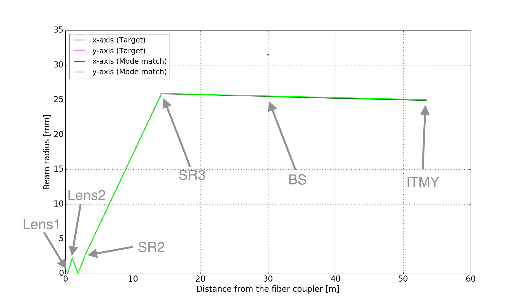
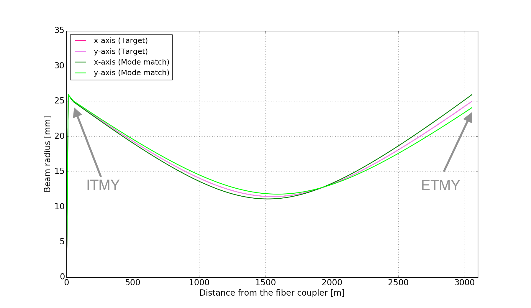
Pattern A (2 lenses)
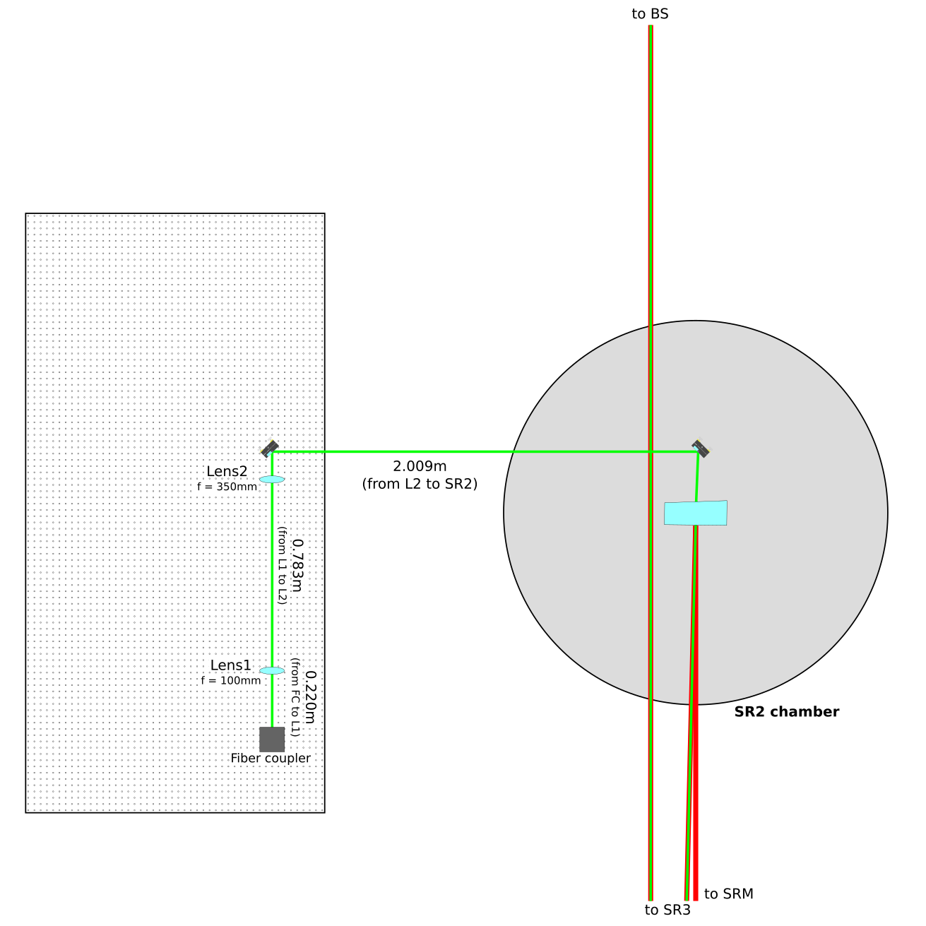
Mirror |
q-parameter |
Waist radius [mm] |
Beam radius [mm] |
|||
qx |
qy |
W0x |
W0y |
Wx |
Wy |
|
Fiber coupler |
0 + 0.723393i |
0.350 |
0.350 |
|||
L1 (Input) |
0.220 + 0.723393i |
0.350 |
0.365828 |
|||
L1 (Output) |
-0.108344 + 0.015935i |
0.051947 |
0.356989 |
|||
L2 (Input) |
0.759858 + 0.016086i |
0.051947 |
2.199920 |
|||
L2 (Output) |
-0.865307 + 0.026488i |
0.066974 |
2.188928 |
|||
SR2 (AR) |
1.143693 + 0.026488i |
0.066974 |
2.892571 |
|||
SR2 (HR) |
1.489013 + 0.040119i |
1.485169 + 0.039991i |
0.082425 |
0.082292 |
3.060270 |
3.057282 |
ITMy (HR) |
-1463.753784 + 729.531387i |
-1538.350364 + 822.405327i |
11.114831 |
11.801137 |
24.917463 |
25.031092 |
ETMy (HR) |
1536.246216 + 729.531387i |
1461.649636 + 822.405327i |
11.114831 |
11.801137 |
25.910643 |
24.066063 |
Pattern B (3 lenses)
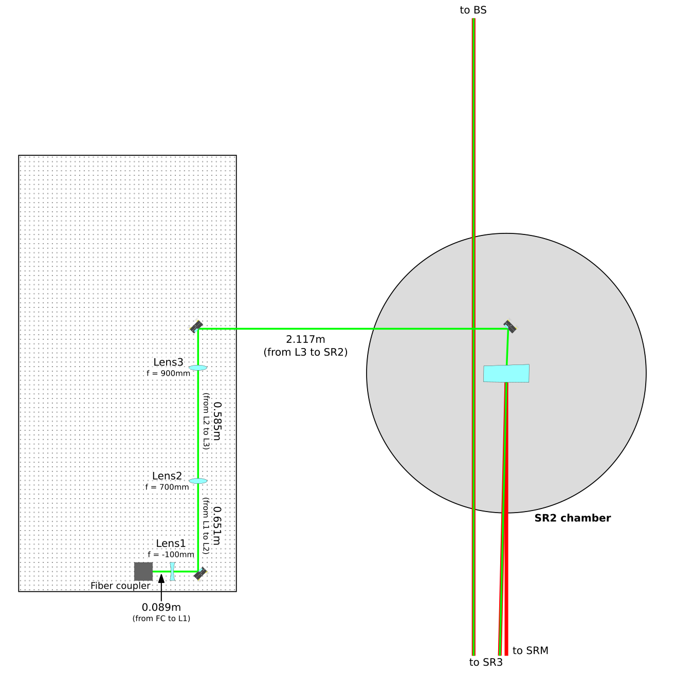
Mirror |
q-parameter |
Waist radius [mm] |
Beam radius [mm] |
|||
qx |
qy |
W0x |
W0y |
Wx |
Wy |
|
Fiber coupler |
0 + 0.723393i |
0.350 |
0.350 |
|||
L1 (Input) |
0.089 + 0.723393i |
0.350 |
0.352639 |
|||
L1 (Output) |
0.108858 + 0.016086i |
0.052192 |
0.357035 |
|||
L2 (Input) |
0.759858 + 0.016086i |
0.052192 |
2.465986 |
|||
L2 (Output) |
0.434746 + 35.905184i |
2.465809 |
2.465990 |
|||
L3 (Input) |
1.019746 + 35.905184i |
2.465809 |
2.466803 |
|||
L3 (Output) |
-0.973312 + 0.026619i |
0.067139 |
2.455838 |
|||
SR2 (AR) |
1.143688 + 0.026619i |
0.067139 |
2.885427 |
|||
SR2 (HR) |
1.489002 + 0.040318i |
1.485159 + 0.040189i |
0.082629 |
0.082496 |
3.052712 |
3.049731 |
ITMy (HR) |
-1461.017819 + 731.892574i |
-1535.118889 + 824.885592i |
11.132804 |
11.818919 |
24.856063 |
24.969411 |
ETMy (HR) |
1538.982181 + 731.892574i |
1464.881111 + 824.885592i |
11.132804 |
11.818919 |
25.921818 |
24.087634 |
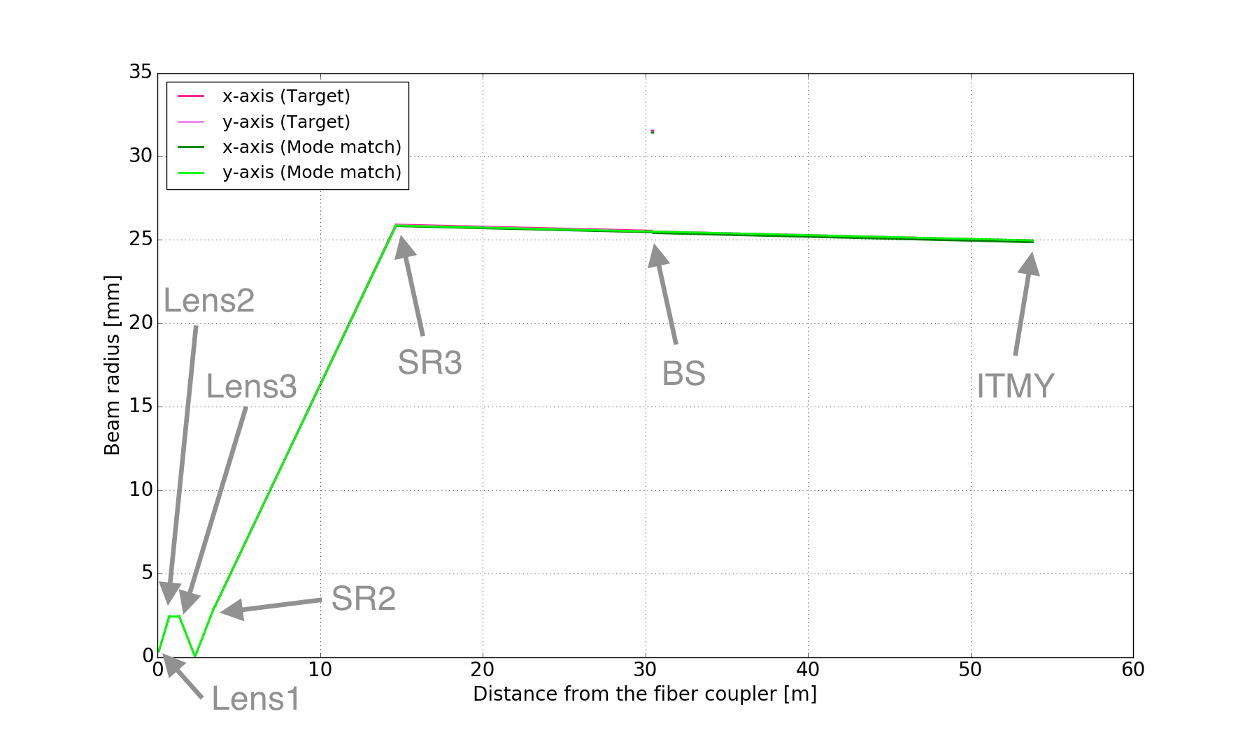
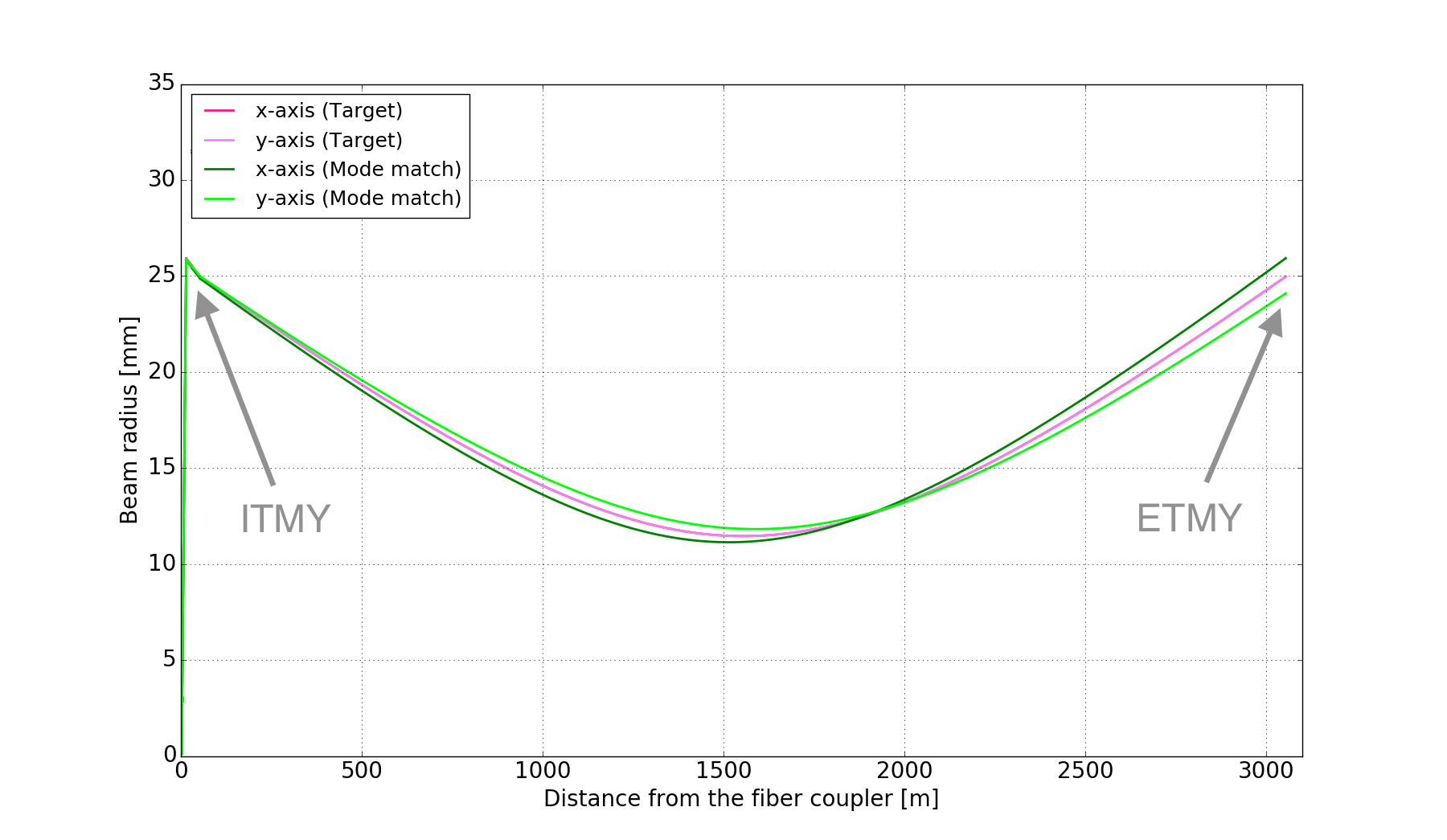
Back of PR2
Lens displacement
For Y-arm
Pattern A (2 lenses)
GreenModeMatch_2lens_170904.pdf
Pattern B (3 lenses)
GreenModeMatch_3lens_170904.pdf
