Arm Cavity Design
RF Sideband resonance in the arm cavities
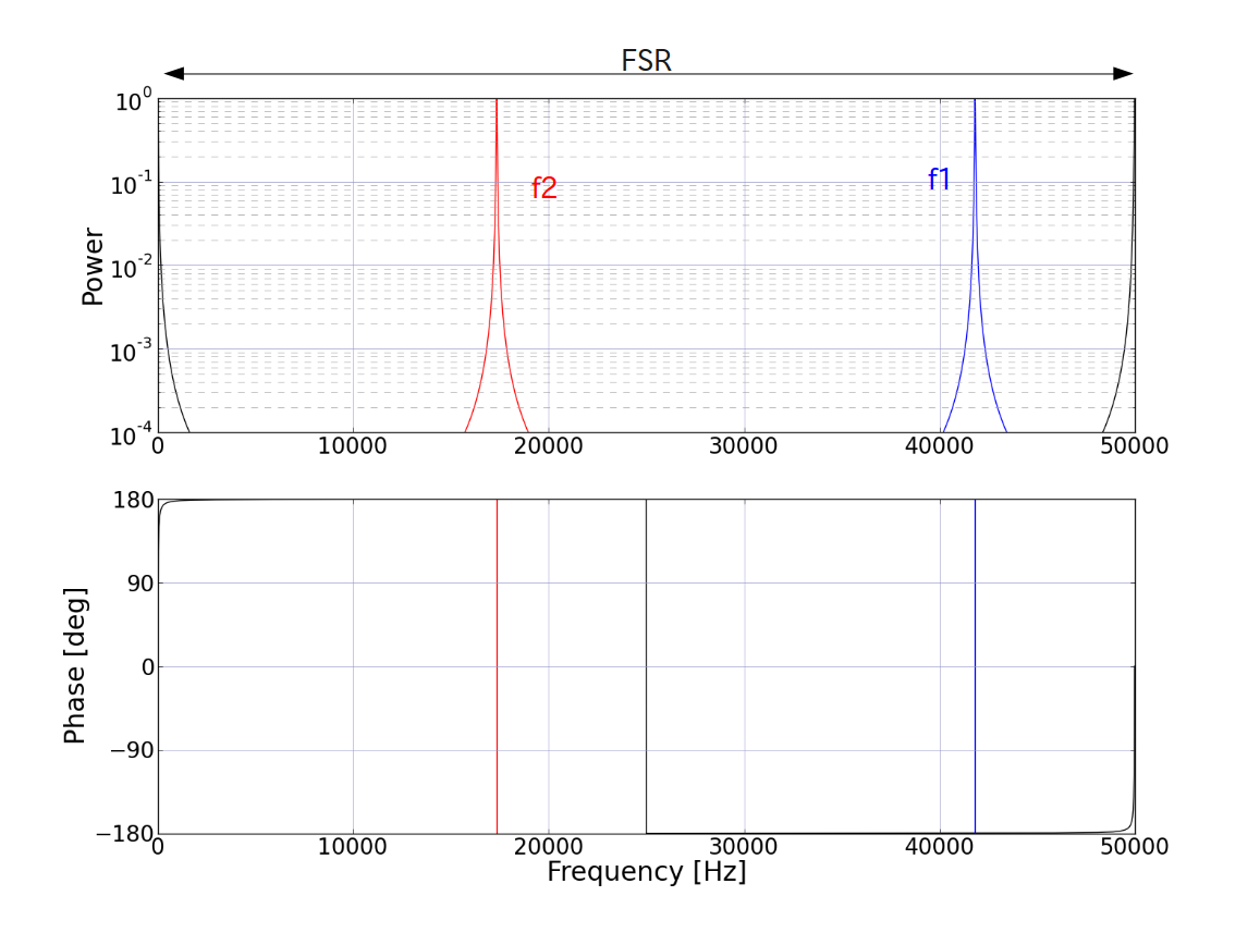
We have to avoid RF sidebands to be resonant in the arm cavities. For example, canonical parameters (L=3000.0, f1=11.25MHz) give the following resonant curves.

Only the upper sidebands are plotted here. It is clear that the two sidebands get different phase shifts when reflected by the arm cavities.
It is desirable to have them both at exactly an anti-resonance. However, it is not possible unless we change the arm length a lot.
So what we aim for are, (1) both sidebands are sufficiently far from the resonances, and (2) both sidebands get the same phase change at the reflection.
By tweaking the MC length (thus the sideband frequencies) a bit (tens of mm), we can find a suitable sideband frequencies which satisfies the above criteria.
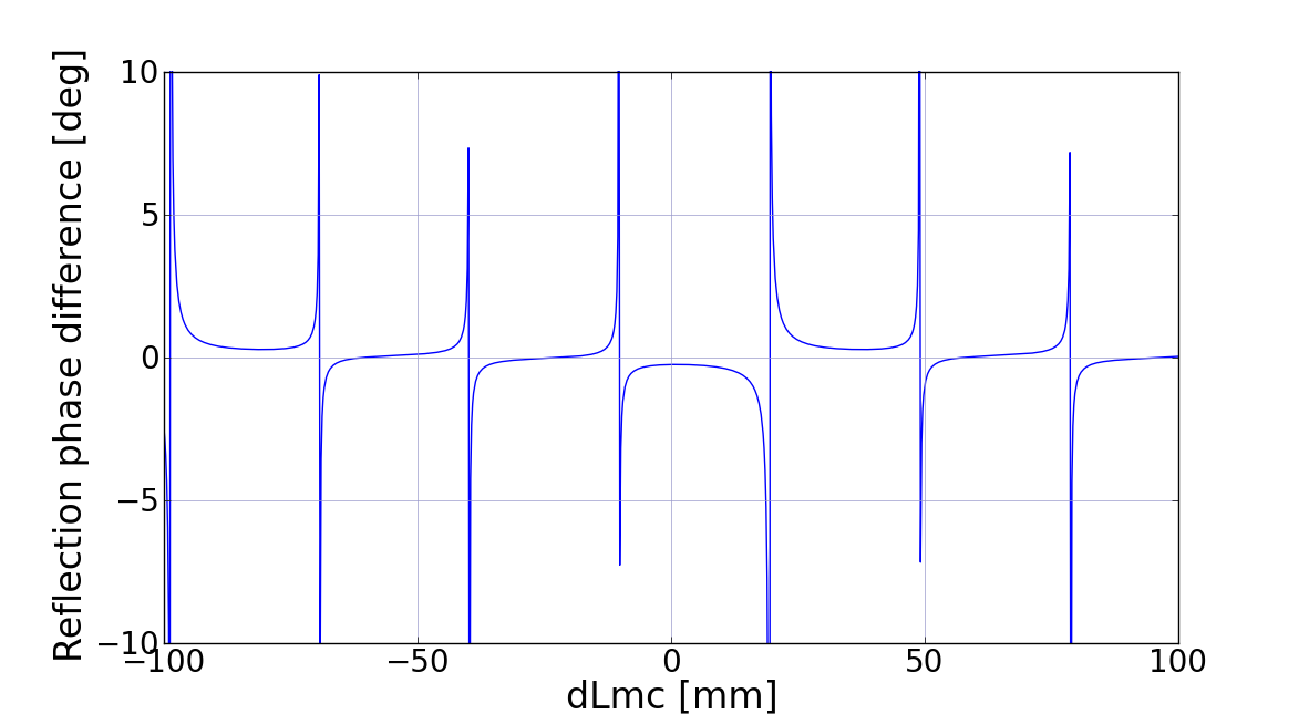
The plot below shows the difference between the reflection phases of the two sidebands as a function of the mode cleaner length's deviation (dLmc) from the canonical length.

There are several zero crossing in the +/-100mm tuning range, the smallest one being around -20mm.
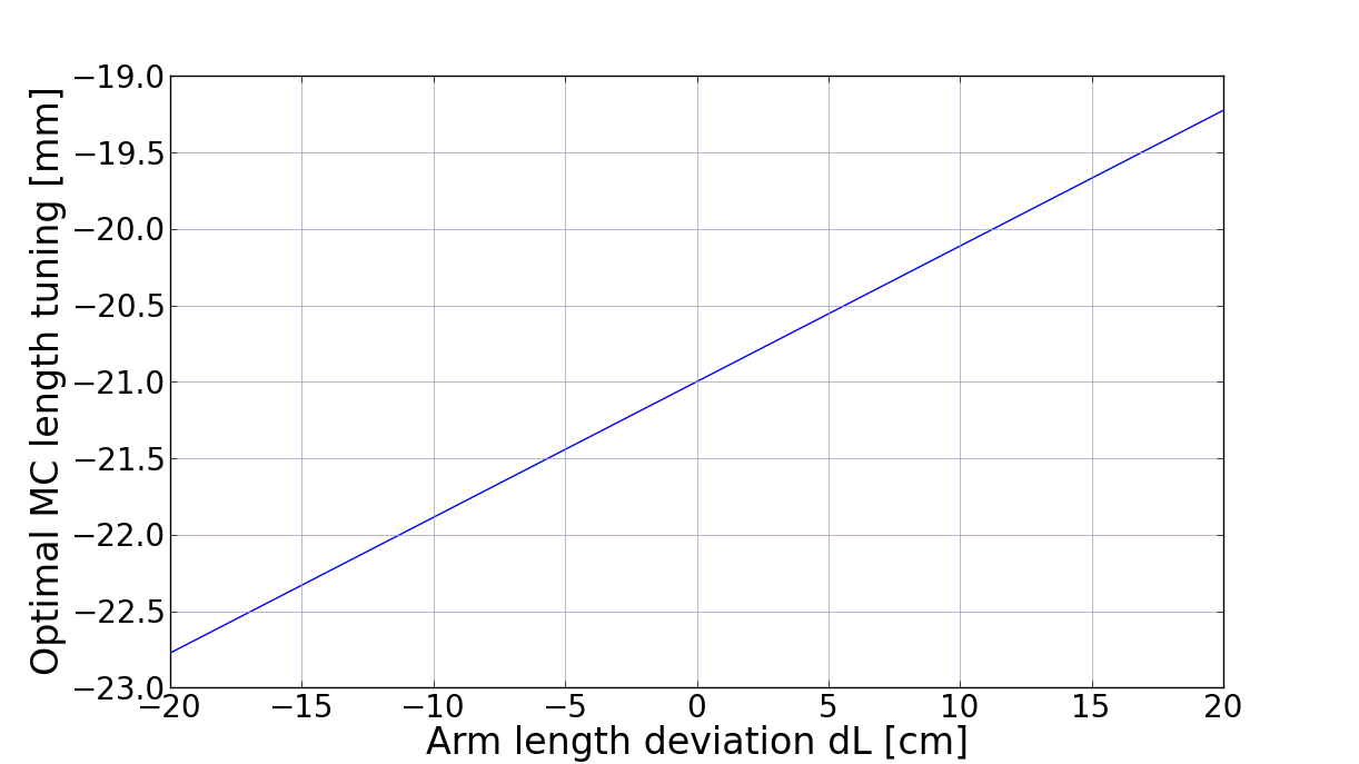
Now, the above plot was made assuming the arm length L is exactly 3000.0m. However, this may not be true. The plot below shows the relation between the deviation of L from 3000.0 and the optimal MC length tuning (dLmc).

With +/-20cm error in the arm length, the optimal MC length changes by 4mm. As we show below, the MC length change translates into the change of Lprc and Lsrc with a factor of 2.25. dLmc=4mm is dLprc=9mm.
MC length and short cavity length
The MC length determines the f1 frequency. The short cavity lengths and asymmetry (Lprc and Lsrc, Las) are in turn determined from the f1 frequency.
The relation between Lmc and f1 is
Lmc = 2*c/(2*f1) = c/f1
Then,
Lprc = Lsrc = 5.5*c/(2*f1) =2.25*Lmc
f2 = 4*f1
Las = c/(2*f2)= Lmc/8
