Type-A Tower ITMY Specification
Contents
IP

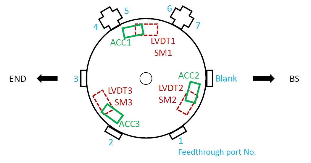
Accelerometer (ACC)
Geophone (GEO) is to be replaced by ACC in ITMX and ITMY.
Frequency response
Geophone's frequency response to the ground velocity:
Sensor |
S/N |
Quality factor |
Resonant frequency [Hz] |
ACC H1 |
# |
|
|
ACC H2 |
# |
|
|
ACC H3 |
# |
|
|
Noise
Sensor |
Noise [m/rtHz] @ 0.1 Hz |
Noise [m/rtHz] @ 10 Hz |
ACC H1 |
|
|
ACC H2 |
|
|
ACC H3 |
|
|
Calibration
Converted displacement [um] = 3.052 x 10⁻⁴ [V/cnt] / HGEO(ω) / (gainPreamp) x (DC cutoff) x 1/s (m/(m/s)) x 106
LVDT
Sensor |
Efficiency [um/cnt] |
LVDT H1 |
|
LVDT H2 |
|
LVDT H3 |
|
Actuator polarization
Polarity is determined so that an +offset at the COILOUTF applies +yaw force in each actuator.
- COIL H1:
- COIL H2:
- COIL H3:
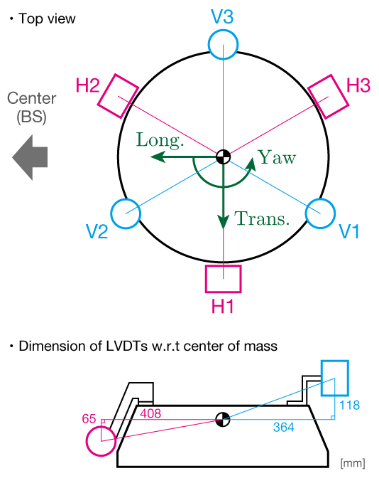
Diagonalization matrix
LVDT2EUL (To be updated)
H1 |
H2 |
H3 |
To: |
0.6666 |
-0.3333 |
-0.3333 |
Long. |
0 |
-0.5774 |
0.5774 |
Trans. |
0.56111 |
0.56111 |
0.56111 |
Yaw |
ACC2EUL (To be updated)
H1 |
H2 |
H3 |
To: |
0.64400 |
-0.17250 |
-0.4714 |
Long. |
0.17250 |
-0.6440 |
0.47140 |
Trans. |
0.56348 |
0.56348 |
0.56348 |
Yaw |
EUL2COIL (To be updated)
Long. |
Trans. |
Yaw |
To: |
0.5 |
0 |
0.594 |
H1 |
-0.25 |
-0.5 |
0.594 |
H2 |
-0.25 |
0.5 |
0.594 |
H3 |
Stepper motor
See also: Stepper motor setup
Epics channel name: K1:STEPPER_IXV_*** |
|||||
Driver IP address: 10.68.150.** |
|||||
Motor 0 |
Motor 1 |
Motor 2 |
Motor 3 |
Motor 4 |
Motor 5 |
F0 Yaw |
IP H1 |
IP H2 |
IP H3 |
<blank> |
<blank> |
GAS
LVDT
Sensor |
Efficiency [um/cnt] |
F0 LVDT GAS |
|
F1 LVDT GAS |
|
F2 LVDT GAS |
|
F3 LVDT GAS |
|
BF LVDT GAS |
|
Fishing Rod (stepper motor)
See also: Stepper motor setup
Motor driver
(To be updated)
Epics channel name: K1:STEPPER_EXV_GAS |
|||||
Driver IP address: 10.68.150.45 |
|||||
Motor 0 |
Motor 1 |
Motor 2 |
Motor 3 |
Motor 4 |
Motor 5 |
F0 GAS |
F1 GAS |
F2 GAS |
F3 GAS |
BF GAS |
<blank> |
Property
(To be updated)
|
F0 GAS |
F1 GAS |
F2 GAS |
F3 GAS |
BF GAS |
Movable range |
mm (± mm) |
(TBC) |
(TBC) |
(TBC) |
full range (± 5.5 mm) |
+step direction |
down |
down |
down |
down |
down |
BF

LVDT (BF Damper)
Sensor |
Efficiency [um/cnt] |
LVDT V1 |
|
LVDT V2 |
|
LVDT V3 |
|
LVDT H1 |
|
LVDT H2 |
|
LVDT H3 |
|
Note: The polarities are determined to output positive signals when the BF shifts respectively to +vertical/+yaw direction for Vertical/Horizontal LVDTs.
Actuator polarization
Polarity is determined so that an +offset at the COILOUTF applies +yaw force in each actuator.
- COIL V1:
- COIL V2:
- COIL V3:
- COIL H1:
- COIL H2:
- COIL H3:
Note: Polarity may change when connecting the secondary coil to the cable. This configuration is confirmed on [2017.10.27]
Diagonalization matrix
LVDT2EUL (To be updated)
V1 |
V2 |
V3 |
H1 |
H2 |
H3 |
To: |
0 |
0 |
0 |
-0.6667 |
0.3333 |
0.3333 |
Long. |
0 |
0 |
0 |
0 |
0.5774 |
-0.5774 |
Trans. |
0.3333 |
0.3333 |
0.3333 |
0 |
0 |
0 |
Vert. |
0.9158 |
0.9158 |
-1.8315 |
0 |
0 |
0 |
Roll |
1.5861 |
-1.5861 |
0 |
0 |
0 |
0 |
Pitch |
0 |
0 |
0 |
0.8170 |
0.8170 |
0.8170 |
Yaw |
EUL2COIL (To be updated)
L |
T |
V |
R |
P |
Y |
To: |
0 |
0 |
1. |
0.1820 |
0.3152 |
0 |
V1 |
0 |
0 |
1. |
0.1820 |
-0.3152 |
0 |
V2 |
0 |
0 |
1. |
-0.3640 |
0 |
0 |
V3 |
-1 |
0 |
0 |
0 |
0 |
0.4080 |
H1 |
0.5 |
0.8660 |
0 |
0 |
0 |
0.4080 |
H2 |
0.5 |
-0.8660 |
0 |
0 |
0 |
0.4080 |
H3 |
Picomotor
See also: Picomotor digital setup
(To be updated)
Epics channel name: K1:PICO_ITMY |
||
Driver IP address: 10.68.150.** |
||
CH1 |
CH2 |
CH3 |
BF moving mass A |
BF moving mass B |
Payload yaw |
- BF moving masses (both A and B ) are currently disabled because of weight limit for upper GAS stages
