|
Size: 6266
Comment:
|
Size: 9108
Comment:
|
| Deletions are marked like this. | Additions are marked like this. |
| Line 7: | Line 7: |
| * [[https://gwdoc.icrr.u-tokyo.ac.jp/cgi-bin/private/DocDB/ShowDocument?docid=6474|Wide Angle Baffle desing review (Obuchi)]] | * [[https://gwdoc.icrr.u-tokyo.ac.jp/cgi-bin/private/DocDB/ShowDocument?docid=6474|Wide Angle Baffle design review (Obuchi)]] |
| Line 12: | Line 12: |
| * [[https://nbviewer.jupyter.org/urls/dl.dropbox.com/s/niycmhy8178ed0y/WAB20170224.ipynb|Personal calc of WAB's stray light noise by Akutsu]]; due to several uncertain parameters there are several results and no one would know the actual effect! | |
| Line 13: | Line 14: |
| Line 37: | Line 39: |
| == PIN Assign == | == Photosensor == The PDs and LED are aligned as shown in the below picture. {{attachment:PS_backside.png|Photosensor head|width="200" }} {{attachment:IMG_4151.jpg|PD and LED pin assign|width="250"}} The following LEDs and PDs are used; thanks for the information from Fukunaga-kun and Ushiba-kun. * [[https://www.thorlabs.co.jp/thorproduct.cfm?partnumber=LED1200E|LED: Thorlabs LED1200E]] * [[https://www.thorlabs.co.jp/thorproduct.cfm?partnumber=FGA21|PD: Thorlabs FGA21]] == Pin Assign == |
| Line 75: | Line 88: |
| ||E||75 ohm|| PS PD || V- || || || × || ||F||75 ohm|| PS PD || V+ || || || × || ||G||4 ohm|| PS LED || I- || || || × || ||H||4 ohm|| PS LED || I+ || || || × || ||J||75 ohm|| PS PD || V- || || || × || ||K||75 ohm|| PS PD || V+ || || || × || ||L||4 ohm|| PS LED || I- || || || × || ||M||4 ohm|| PS LED || I+ || || || × || |
||E||75 ohm|| PS PD || V- (K)|| || || × || ||F||75 ohm|| PS PD || V+ (A)|| || || × || ||G||4 ohm|| PS LED || I- (K)|| || || × || ||H||4 ohm|| PS LED || I+ (A)|| || || × || ||J||75 ohm|| PS PD || V- (K)|| || || × || ||K||75 ohm|| PS PD || V+ (A)|| || || × || ||L||4 ohm|| PS LED || I- (K)|| || || × || ||M||4 ohm|| PS LED || I+ (A)|| || || × || |
| Line 84: | Line 97: |
| ||P||75 ohm|| PS PD || V- || || || × || ||R||75 ohm|| PS PD || V+ || || || × || ||S||4 ohm|| PS LED || I- || || || × || ||T||4 ohm|| PS LED || I+ || || || × || |
||P||75 ohm|| PS PD || V- (K)|| || || × || ||R||75 ohm|| PS PD || V+ (A)|| || || × || ||S||4 ohm|| PS LED || I- (K)|| || || × || ||T||4 ohm|| PS LED || I+ (A)|| || || × || |
| Line 144: | Line 157: |
| === OpLev === | == OpLev == |
| Line 146: | Line 159: |
| * Optical lever installed at the +X/+Y side of the IYC | * Optical lever installed at the +X/-Y side of the IYC |
| Line 148: | Line 161: |
{{attachment:ETMchamber_WAB_oplev_beams3.PNG| Diagram|width="500"}} == WAB Alignment == * Alignment done with 2 laser-leveler inside the IYC * Regarding the used terms: * As the baffle is placed along the Y-arm, +Y and -Y refer to both long ends of the baffle toward the Y-end and toward the center area, respectively! * The same holds true for the horizontal dimension in x-arm direction (+X means toward X-end and -X toward center/PSL) === Yaw === * laser-leveler needs to be close to the -Y main-beam entrance in a height 300 - 400 mm above the optical table * Vertical laser line to be adjusted to the main-beam indication on the optical table and the inner wall of the cryostat * Checked the line by using the slids of the flanges on top the WAB (each slid is ~3.5 mm broad) * For both slids, the laser line is mismatched (not centered) toward -X by ~0.5 mm (@ +Y slid) and ~1 mm (@ -Y slid) That means that there is probably also a -X offset! * The flanges have a distance of 170 mm which indicates a maximum yaw-tilting of ~0.1 degrees '''Note:''' taking the distances is very hard as the position of the slids is not easy to access === Pitch === * laser-leveler outside the cryostat (but inside IYC) set to give a horizontal line along length side of the baffle * Found a slight mismatch for the outer screw holding the OpLev mirrors in +Y,+X and -Y,+X * Difference is ~1 mm (+Z @ -Y, so -Y-side is higher than +Y-side) * With approx. 500 mm distance between both screws, the maximum pitch is ~0.1 degrees === Roll === * Took the height of the OpLev mirror screw-holes (@ -Y,+X and -Y,-X) with a vertical ruler and the horizontal line of the laser-leveler outside the cryostat * Measured a difference of 2.5 mm which makes it a roll of 0.55 degrees (radius of baffle ~130 mm); -Y,-X is higher! * Then took the height of baffle-wings which are mounted on the flanges and could not measure any difference (within an error of 0.5 mm) * Hence, only the baffle is slightly rolled within the flanges! |
Wide Angle Baffle Cooling Test 2018
|
|
|
|||||||||||||||||||||||||||||||||||||||||||||||||||||||||||||||||||||||||||||||||||||||||||||||||||||||||||||||||||||||||||||||||||||||||||||||||||
Links to knowledge
Calculations regarding the back-scattering of different Wide Angle Baffle designs (Zeidler)
Personal calc of WAB's stray light noise by Akutsu; due to several uncertain parameters there are several results and no one would know the actual effect!
Heat links positions (by Obuchi) fmkopgehpapgdkcc.png
Task list
Note: some of the tasks can be done in parallel.
- Place/install the WAB suspension.
- Measure several relative dimensions to get useful information for the future commissioning; concretely speaking:
- What....?
Test the saving mode of the WAB suspension.
Don't forget to replace the damping magnets to SmCo ones.
- What is the requirement to say the damping is sufficient...?
- Connect electric cables (with checking) in the IYC chamber.
3 photosensors; in each photosensor head, two PDs should be connected parallel. Need to calibrate the response of each sensor head...
- 2 heaters; should be connected parallel??
- 1 coil for actuation.
6 thermometers with (extended?) patch cables made of phospher bronze; the extended double twisted pare cables will be delivered on Jan 26
- Connect 4 heat links.
- Check oplev signals.
- Connect cables the outside as well.
- Make a realtime model to monitor.
- Take interface with Tcam.
- Make a plan to do leak check before cooling down.
- Don't forget to add some heat links (Cu?) to the top of the suspension...
Photosensor
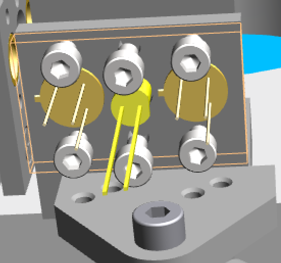
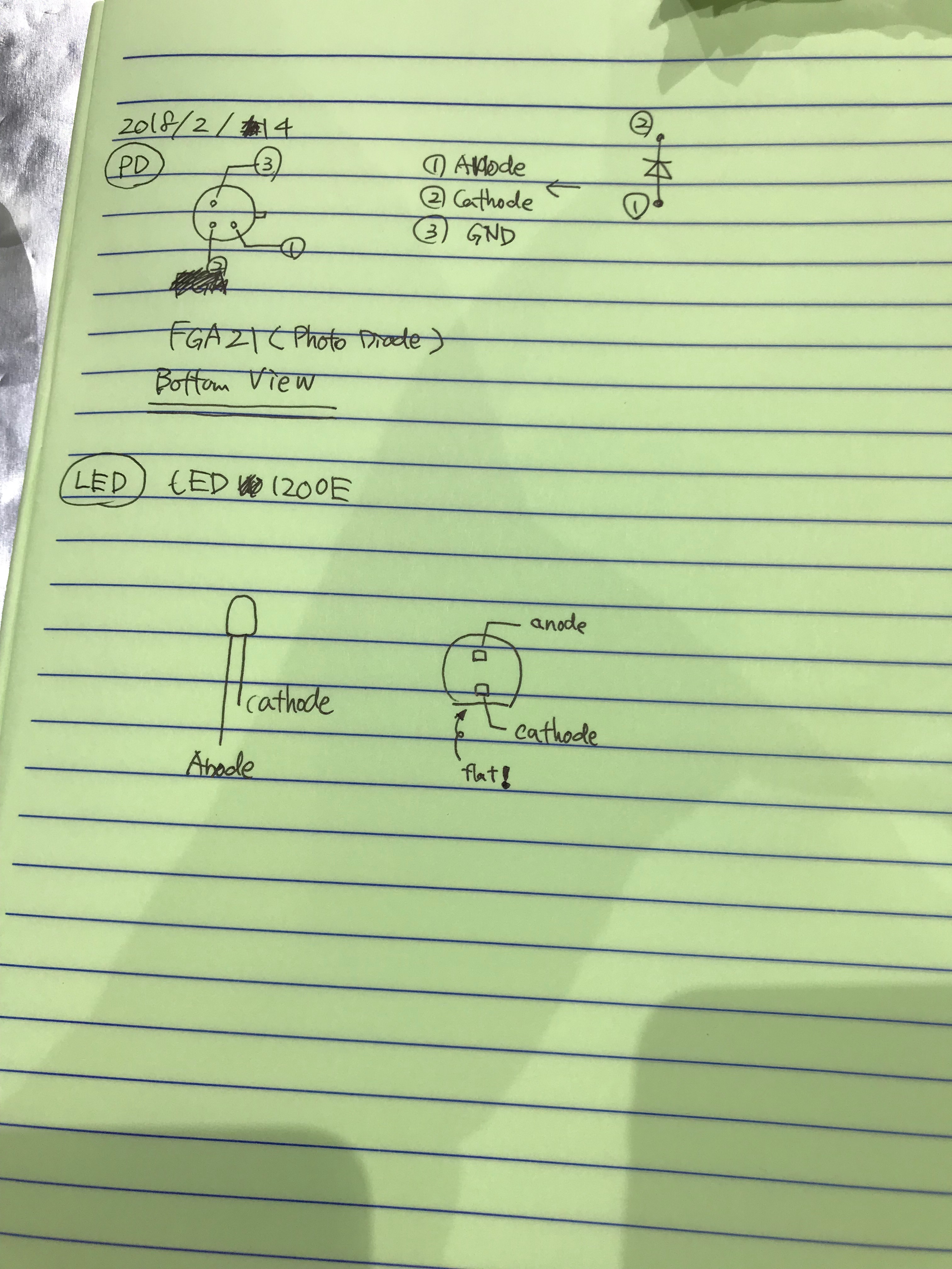
The PDs and LED are aligned as shown in the below picture.


The following LEDs and PDs are used; thanks for the information from Fukunaga-kun and Ushiba-kun.
Pin Assign
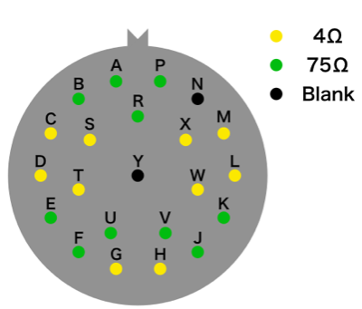
- Summary of the pin assign of burndy connector inside the cryostat.
NOTE: The meaning of color for thermometer cable is
RED = I- , YELLOW = I+ , GREEN = V- , BLACK = V+
P22
Pin Name |
Resistance |
Equipment |
Assign |
Comment1 |
Comment2 |
Connection |
A |
75 ohm |
Thermometer |
V- |
Green |
Cryocon CH A |
○ |
B |
75 ohm |
Thermometer |
V+ |
Black |
|
○ |
C |
4 ohm |
Thermometer |
I- |
Red |
|
○ |
D |
4 ohm |
Thermometer |
I+ |
Yellow |
|
○ |
E |
75 ohm |
Thermometer |
V- |
Green |
Cryocon CH B |
○ |
F |
75 ohm |
Thermometer |
V+ |
Black |
|
○ |
G |
4 ohm |
Thermometer |
I- |
Red |
|
○ |
H |
4 ohm |
Thermometer |
I+ |
Yellow |
|
○ |
J |
75 ohm |
Thermometer |
V- |
Green |
Cryocon CH C |
○ |
K |
75 ohm |
Thermometer |
V+ |
Black |
|
○ |
L |
4 ohm |
Thermometer |
I- |
Red |
|
○ |
M |
4 ohm |
Thermometer |
I+ |
Yellow |
|
○ |
N |
Blank |
|
|
|
|
|
P |
75 ohm |
Thermometer |
V- |
Green |
Cryocon CH D |
○ |
R |
75 ohm |
Thermometer |
V+ |
Black |
|
○ |
S |
4 ohm |
Thermometer |
I- |
Red |
|
○ |
T |
4 ohm |
Thermometer |
I+ |
Yellow |
|
○ |
U |
75 ohm |
Thermometer |
V- |
Green |
Cryocon CH E |
○ |
V |
75 ohm |
Thermometer |
V+ |
Black |
|
○ |
W |
4 ohm |
Thermometer |
I- |
Red |
|
○ |
X |
4 ohm |
Thermometer |
I+ |
Yellow |
|
○ |
Y |
Blank |
|
|
|
|
|
P23
Pin Name |
Resistance |
Equipment |
Assign |
Comment1 |
Comment2 |
Connection |
A |
75 ohm |
Thermometer |
V- |
Green |
Cryocon CH F |
× |
B |
75 ohm |
Thermometer |
V+ |
Black |
|
× |
C |
4 ohm |
Thermometer |
I- |
Red |
|
× |
D |
4 ohm |
Thermometer |
I+ |
Yellow |
|
× |
E |
75 ohm |
PS PD |
V- (K) |
|
|
× |
F |
75 ohm |
PS PD |
V+ (A) |
|
|
× |
G |
4 ohm |
PS LED |
I- (K) |
|
|
× |
H |
4 ohm |
PS LED |
I+ (A) |
|
|
× |
J |
75 ohm |
PS PD |
V- (K) |
|
|
× |
K |
75 ohm |
PS PD |
V+ (A) |
|
|
× |
L |
4 ohm |
PS LED |
I- (K) |
|
|
× |
M |
4 ohm |
PS LED |
I+ (A) |
|
|
× |
N |
Blank |
|
|
|
|
|
P |
75 ohm |
PS PD |
V- (K) |
|
|
× |
R |
75 ohm |
PS PD |
V+ (A) |
|
|
× |
S |
4 ohm |
PS LED |
I- (K) |
|
|
× |
T |
4 ohm |
PS LED |
I+ (A) |
|
|
× |
U |
75 ohm |
CM Act. |
I- |
|
|
× |
V |
75 ohm |
CM Act. |
I+ |
|
|
× |
W |
4 ohm |
Heater |
I- |
|
|
○ |
X |
4 ohm |
Heater |
I+ |
|
|
○ |
Y |
Blank |
|
|
|
|
|

DAQ
Real-time computer: k1???
Slot |
Item |
Assigned to |
S/N |
42 |
<blank> |
|
|
41 |
<blank> |
|
|
40 |
<blank> |
|
|
39 |
<blank> |
|
|
38 |
<blank> |
|
|
37 |
<blank> |
|
|
36 |
<blank> |
|
|
35 |
<blank> |
|
|
34 |
<blank> |
|
|
33 |
<blank> |
|
|
32 |
<blank> |
|
|
31 |
<blank> |
|
|
30 |
<blank> |
|
|
29 |
<blank> |
|
|
28 |
<blank> |
|
|
27 |
<blank> |
|
|
26 |
<blank> |
|
|
25 |
<blank> |
|
|
24 |
<blank> |
|
|
23 |
<blank> |
|
|
22 |
<blank> |
|
|
21 |
<blank> |
|
|
20 |
<blank> |
|
|
19 |
<blank> |
|
|
18 |
<blank> |
|
|
17 |
<blank> |
|
|
16 |
<blank> |
|
|
15 |
<blank> |
|
|
14 |
<blank> |
|
|
13 |
<blank> |
|
|
12 |
AI Chassis |
DAC0 |
SN??? |
11 |
AA Chassis |
ADC0 |
SN??? |
10 |
<blank> |
|
|
9 |
I/O Chassis |
|
SN??? |
8 |
<blank> |
|
|
7 |
<blank> |
|
|
6 |
<blank> |
|
|
5 |
<blank> |
|
|
4 |
<blank> |
|
|
3 |
<blank> |
|
|
2 |
<blank> |
|
|
1 |
<blank> |
|
|
0 |
<blank> |
|
|
OpLev
- Optical lever installed at the +X/-Y side of the IYC
- Path-length inside the chamber (viewport to viewport): ~3000 mm
WAB Alignment
- Alignment done with 2 laser-leveler inside the IYC
- Regarding the used terms:
- As the baffle is placed along the Y-arm, +Y and -Y refer to both long ends of the baffle toward the Y-end and toward the center area, respectively!
- The same holds true for the horizontal dimension in x-arm direction (+X means toward X-end and -X toward center/PSL)
Yaw
- laser-leveler needs to be close to the -Y main-beam entrance in a height 300 - 400 mm above the optical table
- Vertical laser line to be adjusted to the main-beam indication on the optical table and the inner wall of the cryostat
- Checked the line by using the slids of the flanges on top the WAB (each slid is ~3.5 mm broad)
- For both slids, the laser line is mismatched (not centered) toward -X by ~0.5 mm (@ +Y slid) and ~1 mm (@ -Y slid)
That means that there is probably also a -X offset!
- The flanges have a distance of 170 mm which indicates a maximum yaw-tilting of ~0.1 degrees
Note: taking the distances is very hard as the position of the slids is not easy to access
Pitch
- laser-leveler outside the cryostat (but inside IYC) set to give a horizontal line along length side of the baffle
Found a slight mismatch for the outer screw holding the OpLev mirrors in +Y,+X and -Y,+X
- Difference is ~1 mm (+Z @ -Y, so -Y-side is higher than +Y-side)
- With approx. 500 mm distance between both screws, the maximum pitch is ~0.1 degrees
Roll
Took the height of the OpLev mirror screw-holes (@ -Y,+X and -Y,-X) with a vertical ruler and the horizontal line of the laser-leveler outside the cryostat
- Measured a difference of 2.5 mm which makes it a roll of 0.55 degrees (radius of baffle ~130 mm); -Y,-X is higher!
- Then took the height of baffle-wings which are mounted on the flanges and could not measure any difference (within an error of 0.5 mm)
- Hence, only the baffle is slightly rolled within the flanges!
