|
Size: 8578
Comment:
|
← Revision 105 as of 2018-07-18 15:17:37 ⇥
Size: 9851
Comment:
|
| Deletions are marked like this. | Additions are marked like this. |
| Line 3: | Line 3: |
| ||<<MonthCalendar(,2018,1)>>||<<MonthCalendar(,2018,2)>>||<<MonthCalendar(,2018,3)>>|| | ||<<MonthCalendar(,2018,1)>>||<<MonthCalendar(,2018,2)>>||<<MonthCalendar(,2018,3)>>||<<MonthCalendar(,2018,4)>>|| == Important note about data == * [[http://klog.icrr.u-tokyo.ac.jp/osl/?r=4612|Cryocon's misread]] == Coil Injection Time == * [[LCGT/subgroup/AOS/WideAngleBuffle/CoilInjectionTime|Coil Injection Time]] |
| Line 7: | Line 13: |
| * [[https://gwdoc.icrr.u-tokyo.ac.jp/cgi-bin/private/DocDB/ShowDocument?docid=6474|Wide Angle Baffle desing review (Obuchi)]] | * [[https://gwdoc.icrr.u-tokyo.ac.jp/cgi-bin/private/DocDB/ShowDocument?docid=8500|The drawings]] * [[https://gwdoc.icrr.u-tokyo.ac.jp/cgi-bin/private/DocDB/ShowDocument?docid=6474|Wide Angle Baffle design review (Obuchi)]] |
| Line 15: | Line 22: |
| Line 19: | Line 27: |
| * Place/install the WAB suspension. * Measure several relative dimensions to get useful information for the future commissioning; concretely speaking: |
* --(Place/install the WAB suspension.)-- * --(Measure several relative dimensions to get useful information for the future commissioning; concretely speaking:)-- |
| Line 22: | Line 30: |
| * Test the '''''saving mode''''' of the WAB suspension. * Don't forget to replace the damping magnets to SmCo ones. |
* --(Test the '''''saving mode''''' of the WAB suspension.)-- * --(Don't forget to replace the damping magnets to SmCo ones. )-- |
| Line 25: | Line 33: |
| * Connect electric cables (with checking) in the IYC chamber. * 3 photosensors; in each photosensor head, two PDs should be connected parallel. '''''Need to calibrate the response of each sensor head...''''' * 2 heaters; should be connected parallel?? * 1 coil for actuation. * 6 thermometers with (extended?) patch cables made of phospher bronze; the extended double twisted pare cables will be delivered on '''''Jan 26''''' * Connect 4 heat links. * Check oplev signals. * Connect cables the outside as well. * Make a realtime model to monitor. * Take interface with Tcam. * Make a plan to do leak check before cooling down. * Don't forget to add some heat links (Cu?) to the top of the suspension... == PIN Assign == |
* --(Connect electric cables (with checking) in the IYC chamber.)-- * --(3 photosensors; in each photosensor head, two PDs should be connected parallel. '''''Need to calibrate the response of each sensor head...''''')-- * --(2 heaters; should be connected parallel??)-- * --(1 coil for actuation.)-- * --(6 thermometers with (extended?) patch cables made of phospher bronze; the extended double twisted pare cables will be delivered on '''''Jan 26''''')-- * --(Connect 4 heat links.)-- * --(Check oplev signals.)-- * --(Connect cables the outside as well.)-- * --(Make a realtime model to monitor.)-- * --(Take interface with Tcam.)-- * --(Make a plan to do leak check before cooling down.)-- * --(Don't forget to add some heat links (Cu?) to the top of the suspension...)-- * --(Remove the Heat-Link block)-- == Photosensor == The PDs and LED are aligned as shown in the below picture. {{attachment:PS_backside.png|Photosensor head|width="200" }} {{attachment:IMG_4151.jpg|PD and LED pin assign|width="250"}} The following LEDs and PDs are used; thanks for the information from Fukunaga-kun and Ushiba-kun. * [[https://www.thorlabs.co.jp/thorproduct.cfm?partnumber=LED1200E|LED: Thorlabs LED1200E]] * [[https://www.thorlabs.co.jp/thorproduct.cfm?partnumber=FGA21|PD: Thorlabs FGA21]] OSEM satellite amp is used to drive. * [[https://gwdoc.icrr.u-tokyo.ac.jp/cgi-bin/private/DocDB/ShowDocument?docid=3499]] == Pin Assign == |
| Line 72: | Line 95: |
| ||A||75 ohm|| Thermometer || V- || Green || Cryocon CH F || × || ||B||75 ohm|| Thermometer || V+ || Black || || × || ||C||4 ohm|| Thermometer || I- || Red || || × || ||D||4 ohm|| Thermometer || I+ || Yellow || || × || ||E||75 ohm|| PS PD || V- || || || × || ||F||75 ohm|| PS PD || V+ || || || × || ||G||4 ohm|| PS LED || I- || || || × || ||H||4 ohm|| PS LED || I+ || || || × || ||J||75 ohm|| PS PD || V- || || || × || ||K||75 ohm|| PS PD || V+ || || || × || ||L||4 ohm|| PS LED || I- || || || × || ||M||4 ohm|| PS LED || I+ || || || × || |
||A||75 ohm|| Thermometer || V- || Green || Cryocon CH F || ○ || ||B||75 ohm|| Thermometer || V+ || Black || || ○ || ||C||4 ohm|| Coil Mag. Act. || I- || || ''As low resistor line was needed.'' || ○ || ||D||4 ohm|| Coil Mag. Act. || I+ || || ''As low resistor line was needed.'' || ○ || ||E||75 ohm|| PS1 PD || V- (K)|| || || ○ || ||F||75 ohm|| PS1 PD || V+ (A)|| || || ○ || ||G||4 ohm|| PS1 LED || I- (K)|| || || ○ || ||H||4 ohm|| PS1 LED || I+ (A)|| || || ○ || ||J||75 ohm|| PS2 PD || V- (K)|| || || ○ || ||K||75 ohm|| PS2 PD || V+ (A)|| || || ○ || ||L||4 ohm|| PS2 LED || I- (K)|| || || ○ || ||M||4 ohm|| PS2 LED || I+ (A)|| || || ○ || |
| Line 85: | Line 108: |
| ||P||75 ohm|| PS PD || V- || || || × || ||R||75 ohm|| PS PD || V+ || || || × || ||S||4 ohm|| PS LED || I- || || || × || ||T||4 ohm|| PS LED || I+ || || || × || ||U||75 ohm|| CM Act. || I- || || || × || ||V||75 ohm|| CM Act. || I+ || || || × || |
||P||75 ohm|| PS3 PD || V- (K)|| || || ○ || ||R||75 ohm|| PS3 PD || V+ (A)|| || || ○ || ||S||4 ohm|| PS3 LED || I- (K)|| || || ○ || ||T||4 ohm|| PS3 LED || I+ (A)|| || || ○ || ||U||75 ohm|| Thermometer || I- || Red|| Cryocon CH F || ○ || ||V||75 ohm|| Thermometer || I+ || Yellow || Cryocon CH F || ○ || |
| Line 156: | Line 179: |
| 1. As the baffle is placed along the Y-arm, +Y and -Y refer to both long ends of the baffle toward the Y-end and toward the center area, respectively! 2. The same holds true for the horizontal dimension in x-arm direction (+X means toward X-end and -X toward center/PSL) |
* As the baffle is placed along the Y-arm, +Y and -Y refer to both long ends of the baffle toward the Y-end and toward the center area, respectively! * The same holds true for the horizontal dimension in x-arm direction (+X means toward X-end and -X toward center/PSL) |
Wide Angle Baffle Cooling Test 2018
|
|
|
|
|||||||||||||||||||||||||||||||||||||||||||||||||||||||||||||||||||||||||||||||||||||||||||||||||||||||||||||||||||||||||||||||||||||||||||||||||||||||||||||||||||||||||||||||||||||||||||||||||||||||||||
Important note about data
Coil Injection Time
Links to knowledge
Calculations regarding the back-scattering of different Wide Angle Baffle designs (Zeidler)
Personal calc of WAB's stray light noise by Akutsu; due to several uncertain parameters there are several results and no one would know the actual effect!
Heat links positions (by Obuchi) fmkopgehpapgdkcc.png
Task list
Note: some of the tasks can be done in parallel.
Place/install the WAB suspension.
Measure several relative dimensions to get useful information for the future commissioning; concretely speaking:
- What....?
Test the saving mode of the WAB suspension.
Don't forget to replace the damping magnets to SmCo ones.
- What is the requirement to say the damping is sufficient...?
Connect electric cables (with checking) in the IYC chamber.
3 photosensors; in each photosensor head, two PDs should be connected parallel. Need to calibrate the response of each sensor head...
2 heaters; should be connected parallel??
1 coil for actuation.
6 thermometers with (extended?) patch cables made of phospher bronze; the extended double twisted pare cables will be delivered on Jan 26
Connect 4 heat links.
Check oplev signals.
Connect cables the outside as well.
Make a realtime model to monitor.
Take interface with Tcam.
Make a plan to do leak check before cooling down.
Don't forget to add some heat links (Cu?) to the top of the suspension...
Remove the Heat-Link block
Photosensor
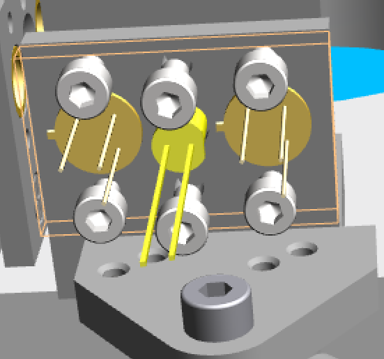
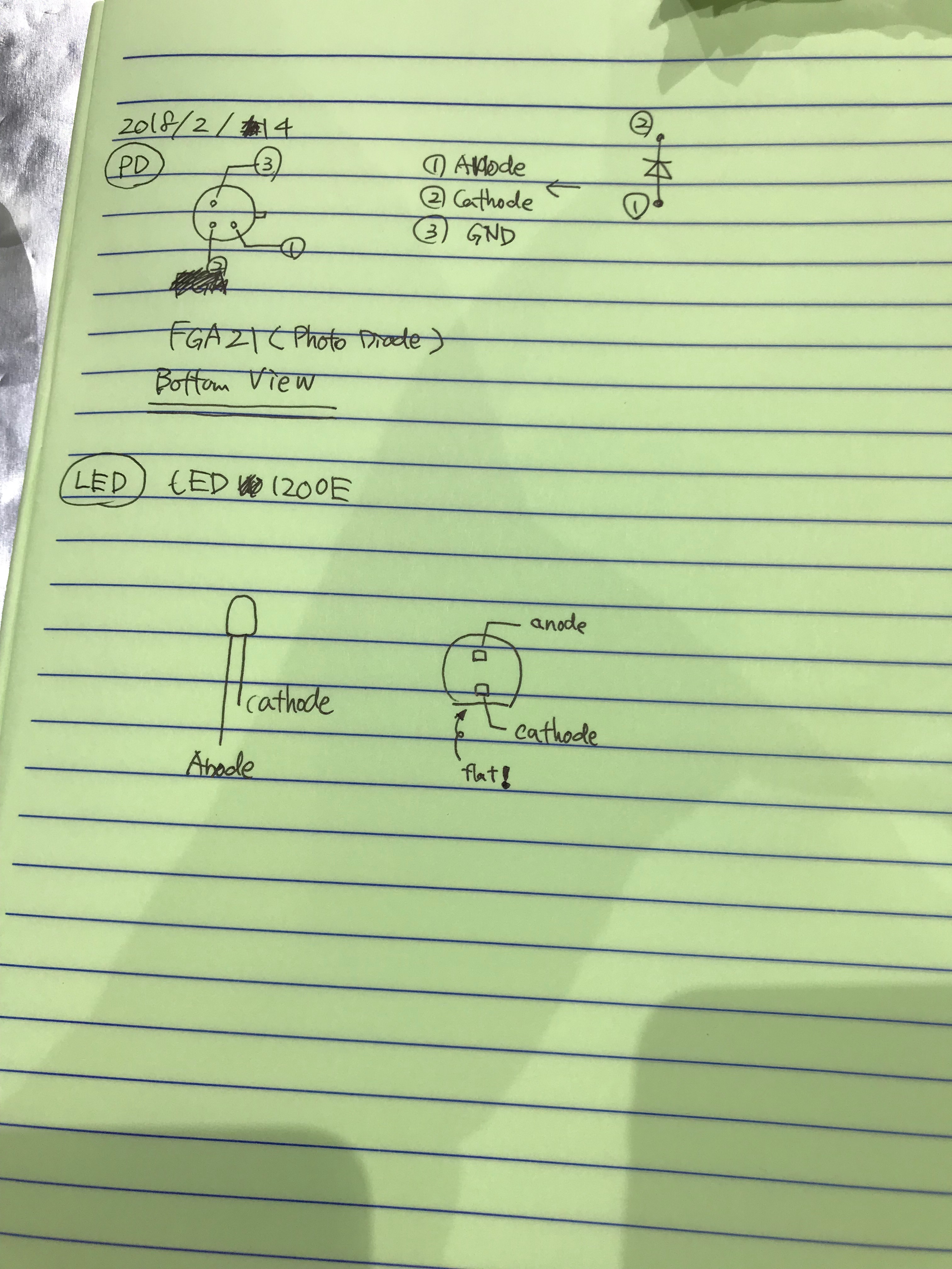
The PDs and LED are aligned as shown in the below picture.


The following LEDs and PDs are used; thanks for the information from Fukunaga-kun and Ushiba-kun.
OSEM satellite amp is used to drive.
Pin Assign
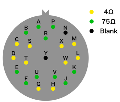
- Summary of the pin assign of burndy connector inside the cryostat.
NOTE: The meaning of color for thermometer cable is
RED = I- , YELLOW = I+ , GREEN = V- , BLACK = V+
P22
Pin Name |
Resistance |
Equipment |
Assign |
Comment1 |
Comment2 |
Connection |
A |
75 ohm |
Thermometer |
V- |
Green |
Cryocon CH A |
○ |
B |
75 ohm |
Thermometer |
V+ |
Black |
|
○ |
C |
4 ohm |
Thermometer |
I- |
Red |
|
○ |
D |
4 ohm |
Thermometer |
I+ |
Yellow |
|
○ |
E |
75 ohm |
Thermometer |
V- |
Green |
Cryocon CH B |
○ |
F |
75 ohm |
Thermometer |
V+ |
Black |
|
○ |
G |
4 ohm |
Thermometer |
I- |
Red |
|
○ |
H |
4 ohm |
Thermometer |
I+ |
Yellow |
|
○ |
J |
75 ohm |
Thermometer |
V- |
Green |
Cryocon CH C |
○ |
K |
75 ohm |
Thermometer |
V+ |
Black |
|
○ |
L |
4 ohm |
Thermometer |
I- |
Red |
|
○ |
M |
4 ohm |
Thermometer |
I+ |
Yellow |
|
○ |
N |
Blank |
|
|
|
|
|
P |
75 ohm |
Thermometer |
V- |
Green |
Cryocon CH D |
○ |
R |
75 ohm |
Thermometer |
V+ |
Black |
|
○ |
S |
4 ohm |
Thermometer |
I- |
Red |
|
○ |
T |
4 ohm |
Thermometer |
I+ |
Yellow |
|
○ |
U |
75 ohm |
Thermometer |
V- |
Green |
Cryocon CH E |
○ |
V |
75 ohm |
Thermometer |
V+ |
Black |
|
○ |
W |
4 ohm |
Thermometer |
I- |
Red |
|
○ |
X |
4 ohm |
Thermometer |
I+ |
Yellow |
|
○ |
Y |
Blank |
|
|
|
|
|
P23
Pin Name |
Resistance |
Equipment |
Assign |
Comment1 |
Comment2 |
Connection |
A |
75 ohm |
Thermometer |
V- |
Green |
Cryocon CH F |
○ |
B |
75 ohm |
Thermometer |
V+ |
Black |
|
○ |
C |
4 ohm |
Coil Mag. Act. |
I- |
|
As low resistor line was needed. |
○ |
D |
4 ohm |
Coil Mag. Act. |
I+ |
|
As low resistor line was needed. |
○ |
E |
75 ohm |
PS1 PD |
V- (K) |
|
|
○ |
F |
75 ohm |
PS1 PD |
V+ (A) |
|
|
○ |
G |
4 ohm |
PS1 LED |
I- (K) |
|
|
○ |
H |
4 ohm |
PS1 LED |
I+ (A) |
|
|
○ |
J |
75 ohm |
PS2 PD |
V- (K) |
|
|
○ |
K |
75 ohm |
PS2 PD |
V+ (A) |
|
|
○ |
L |
4 ohm |
PS2 LED |
I- (K) |
|
|
○ |
M |
4 ohm |
PS2 LED |
I+ (A) |
|
|
○ |
N |
Blank |
|
|
|
|
|
P |
75 ohm |
PS3 PD |
V- (K) |
|
|
○ |
R |
75 ohm |
PS3 PD |
V+ (A) |
|
|
○ |
S |
4 ohm |
PS3 LED |
I- (K) |
|
|
○ |
T |
4 ohm |
PS3 LED |
I+ (A) |
|
|
○ |
U |
75 ohm |
Thermometer |
I- |
Red |
Cryocon CH F |
○ |
V |
75 ohm |
Thermometer |
I+ |
Yellow |
Cryocon CH F |
○ |
W |
4 ohm |
Heater |
I- |
|
|
○ |
X |
4 ohm |
Heater |
I+ |
|
|
○ |
Y |
Blank |
|
|
|
|
|

DAQ
Real-time computer: k1???
Slot |
Item |
Assigned to |
S/N |
42 |
<blank> |
|
|
41 |
<blank> |
|
|
40 |
<blank> |
|
|
39 |
<blank> |
|
|
38 |
<blank> |
|
|
37 |
<blank> |
|
|
36 |
<blank> |
|
|
35 |
<blank> |
|
|
34 |
<blank> |
|
|
33 |
<blank> |
|
|
32 |
<blank> |
|
|
31 |
<blank> |
|
|
30 |
<blank> |
|
|
29 |
<blank> |
|
|
28 |
<blank> |
|
|
27 |
<blank> |
|
|
26 |
<blank> |
|
|
25 |
<blank> |
|
|
24 |
<blank> |
|
|
23 |
<blank> |
|
|
22 |
<blank> |
|
|
21 |
<blank> |
|
|
20 |
<blank> |
|
|
19 |
<blank> |
|
|
18 |
<blank> |
|
|
17 |
<blank> |
|
|
16 |
<blank> |
|
|
15 |
<blank> |
|
|
14 |
<blank> |
|
|
13 |
<blank> |
|
|
12 |
AI Chassis |
DAC0 |
SN??? |
11 |
AA Chassis |
ADC0 |
SN??? |
10 |
<blank> |
|
|
9 |
I/O Chassis |
|
SN??? |
8 |
<blank> |
|
|
7 |
<blank> |
|
|
6 |
<blank> |
|
|
5 |
<blank> |
|
|
4 |
<blank> |
|
|
3 |
<blank> |
|
|
2 |
<blank> |
|
|
1 |
<blank> |
|
|
0 |
<blank> |
|
|
OpLev
- Optical lever installed at the +X/-Y side of the IYC
- Path-length inside the chamber (viewport to viewport): ~3000 mm
WAB Alignment
- Alignment done with 2 laser-leveler inside the IYC
- Regarding the used terms:
- As the baffle is placed along the Y-arm, +Y and -Y refer to both long ends of the baffle toward the Y-end and toward the center area, respectively!
- The same holds true for the horizontal dimension in x-arm direction (+X means toward X-end and -X toward center/PSL)
Yaw
- laser-leveler needs to be close to the -Y main-beam entrance in a height 300 - 400 mm above the optical table
- Vertical laser line to be adjusted to the main-beam indication on the optical table and the inner wall of the cryostat
- Checked the line by using the slids of the flanges on top the WAB (each slid is ~3.5 mm broad)
- For both slids, the laser line is mismatched (not centered) toward -X by ~0.5 mm (@ +Y slid) and ~1 mm (@ -Y slid)
That means that there is probably also a -X offset!
- The flanges have a distance of 170 mm which indicates a maximum yaw-tilting of ~0.1 degrees
Note: taking the distances is very hard as the position of the slids is not easy to access
Pitch
- laser-leveler outside the cryostat (but inside IYC) set to give a horizontal line along length side of the baffle
Found a slight mismatch for the outer screw holding the OpLev mirrors in +Y,+X and -Y,+X
- Difference is ~1 mm (+Z @ -Y, so -Y-side is higher than +Y-side)
- With approx. 500 mm distance between both screws, the maximum pitch is ~0.1 degrees
Roll
Took the height of the OpLev mirror screw-holes (@ -Y,+X and -Y,-X) with a vertical ruler and the horizontal line of the laser-leveler outside the cryostat
- Measured a difference of 2.5 mm which makes it a roll of 0.55 degrees (radius of baffle ~130 mm); -Y,-X is higher!
- Then took the height of baffle-wings which are mounted on the flanges and could not measure any difference (within an error of 0.5 mm)
- Hence, only the baffle is slightly rolled within the flanges!
